Talos bright-field and dark-field imaging
Caution
VERY ROUGH DRAFT. Notes from a Stanford MATSCI 322 TEM Lab session taught by Andrew Barnum, Pinaki Mukherjee, and Ash. This guide is being expanded and refined as @bobleesj uses the Talos in future sessions. Steps and screenshots still need verification against the live instrument.
TODO: Add stage navigation, eucentric height alignment, selected-area aperture insertion, condenser aperture changes, dose-on-sample calibration, and end-of-session shutdown.
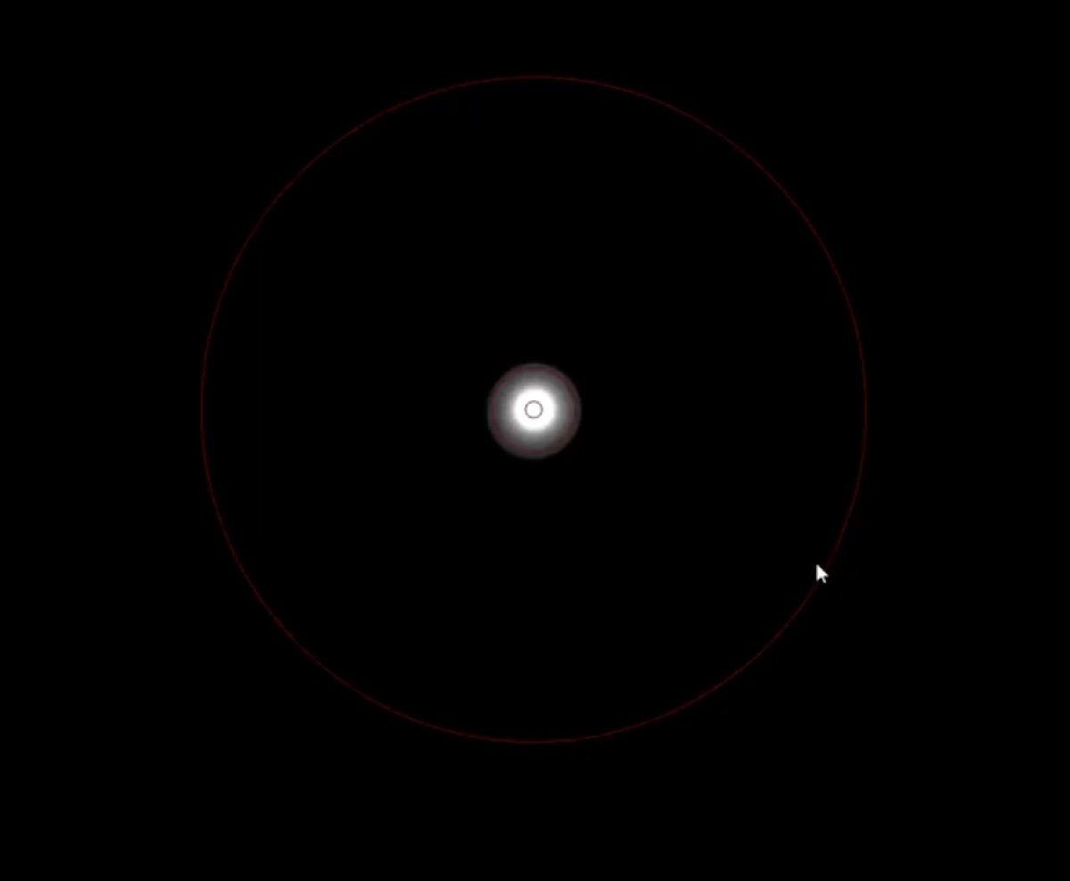
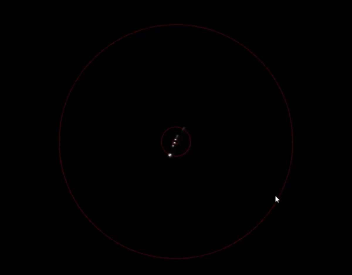
This guide covers the operational steps for bright-field (BF) and dark-field (DF) imaging on the Talos TEM, captured during a class session in April 2026. It also includes a reference example of how under- and over-focused images appear on the FluCam, which is useful when interpreting defocus during alignment.
Acronyms:
BF: bright fieldDF: dark fieldTEM: transmission electron microscopeSTEM: scanning transmission electron microscopeFFT: fast Fourier transformVelox: Thermo Fisher acquisition software for the TalosFluCam/SmartCam: fluorescent screen camera (used for alignment)Ceta: high-resolution CMOS camera mounted below the phosphor screenmulXY: multi-function X/Y knobs on the hand panel
Overview
| Phase | What it covers | Time |
|---|---|---|
| Part 1: Startup and orientation | System settle, identify legacy hardware, vacuum check | 5 min |
| Part 2: Open Velox and select a camera | Launch Velox, choose FluCam or Ceta | 2 min |
| Part 3: Configure acquisition parameters | Frame size, frame combining, shutter, recording mode | 3 min |
| Part 4: Bright-field imaging | Open valves, navigate, set illumination, annotate | varies |
| Part 5: Dark-field imaging | Beam tilt, dark-field toggle, BF/DF comparison | 10 min |
Part 1: Startup and orientation
1.1 Allow the system to settle
-
Wait for the column to reach steady state
- Wait 2 to 3 minutes after powering up the Talos console before interacting with the column.
- Confirm the vacuum and high-tension subsystems have stabilized.
1.2 Locate the legacy hardware buttons
-
Identify the legacy controls on the console
-
Identify the legacy hardware buttons on the console. These exist because, before live FFT was available, focus had to be judged on the phosphor screen using the “Wobbler” feature, which modulates the beam to highlight the focused condition.
-
Use the live FFT in
Veloxfor routine focusing. The legacy controls remain functional as a backup.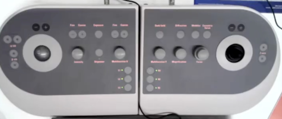
-
1.3 Check the vacuum overview
-
Confirm vacuum status
-
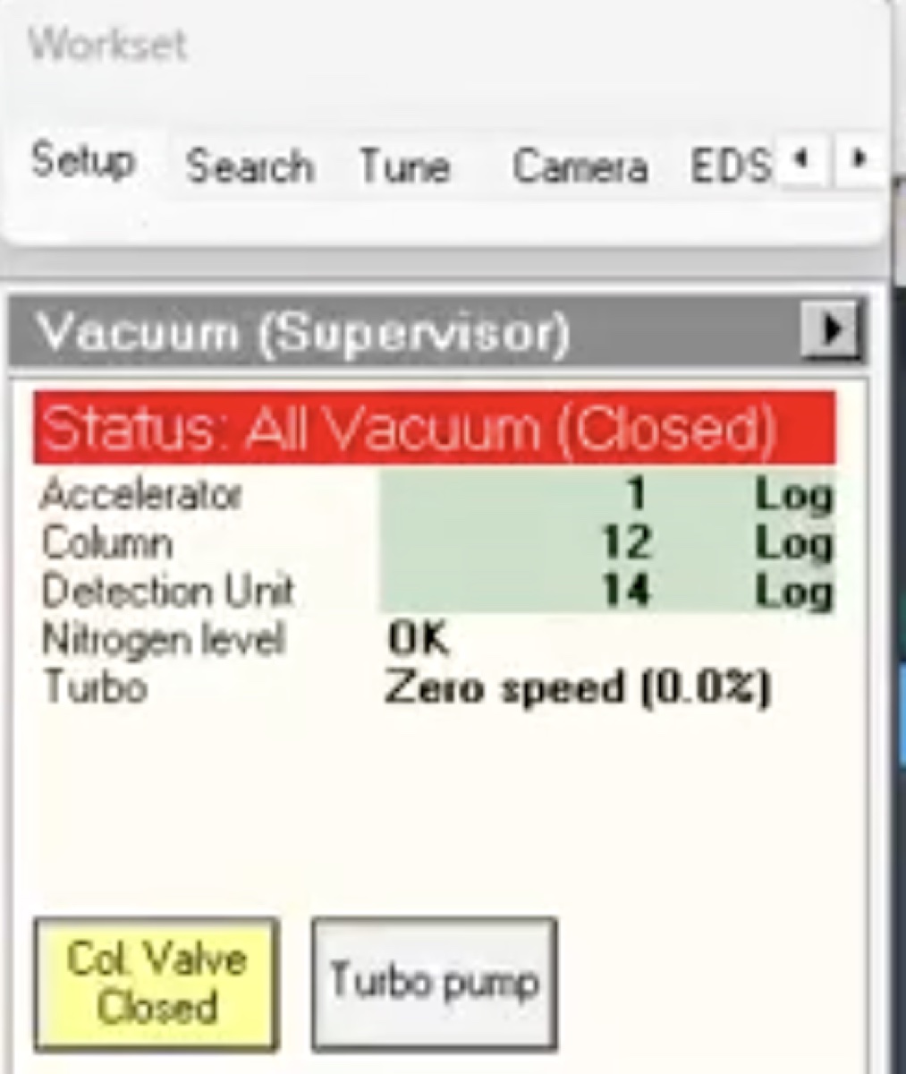
Open the Talos UI vacuum overview panel.
-
Confirm the column vacuum reads green before opening the column valves.
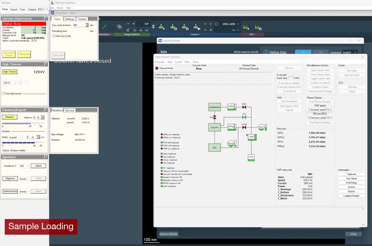
CRITICAL: Do not proceed if any vacuum gauge is yellow or red. Contact staff.
-
Part 2: Open Velox and select a camera
2.1 Launch Velox
-
Open the Velox acquisition software
-
Launch
Veloxfrom the desktop.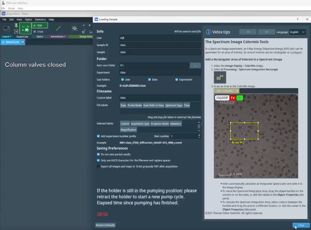
-
2.2 Select the FluCam for initial setup
-
Use the FluCam during alignment
- Select the
FluCam(also labeledSmartCamin some menus) for initial setup and alignment. The FluCam points at the phosphor screen rather than receiving the direct beam. - Use this camera for any operations that risk a high beam dose, since it protects the more expensive
CetaCMOS camera underneath.
- Select the
2.3 Switch to the Ceta camera for final acquisition
-
Switch to Ceta when alignment is satisfactory
-
Switch to the
Cetacamera once the alignment is complete and a high-resolution image is required.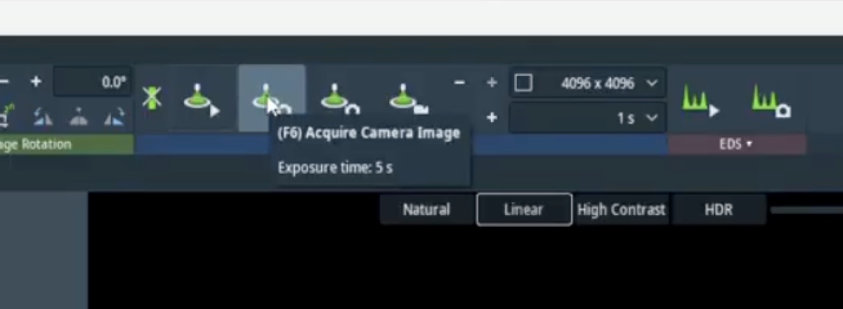
-
Part 3: Configure acquisition parameters
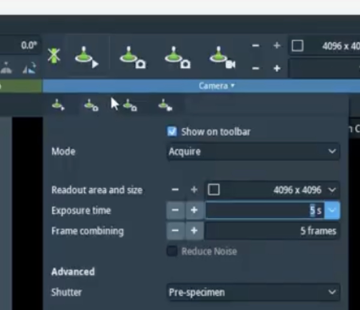
3.1 Open the acquisition presets
-
Open both acquisition presets
-
Open the two acquisition presets in
Velox. -
Update the parameters in each preset as needed during the session.
-
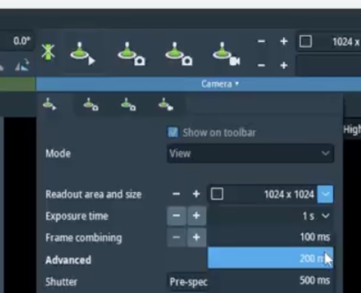
3.2 Set frame size and frame combining
-
Set 1024 by 1024 frames with 200 ms combining
-
Set the frame size to 1024 by 1024 pixels.
-
Set the frame combining to 200 ms. Frame combining averages multiple short exposures into a single output frame, which improves signal-to-noise without committing to one long exposure.
-
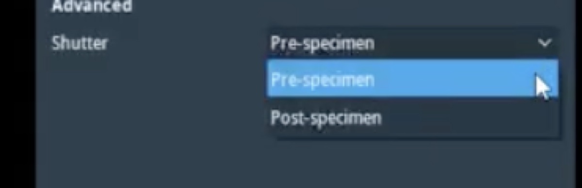
3.3 Choose the shutter
-
Pick pre-specimen or post-specimen shutter
-
Choose the pre-specimen shutter to block the beam before it reaches the sample. This protects beam-sensitive samples between exposures.
-
Choose the post-specimen shutter (a projection blanker) to block the beam after the sample. This controls exposure on the camera without changing illumination on the sample.
-
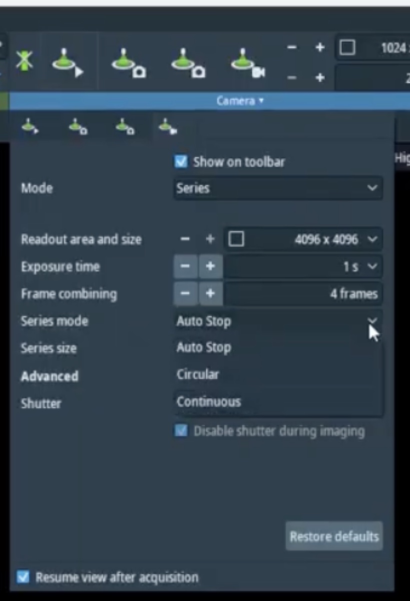
3.4 Choose the recording mode
-
Pick the recording mode that matches the experiment
-
Choose Auto Stop to record a fixed number of frames and then halt. This is the default for still imaging.
-
Choose Circular to keep the most recent N frames in a rolling memory buffer; pressing stop preserves whatever is in the buffer. This is useful for in-situ experiments where the moment of interest is unpredictable.
-
Choose Continuous to save every frame for the full duration of the recording.
-
3.5 Open the column status bar
-
Show the column status bar during acquisition
-
Open the column status bar so the beam state, vacuum, and stage coordinates remain visible during acquisition.
-
Part 4: Bright-field imaging
4.1 Open the column valves
-
Open the column valves once vacuum is green
-
Open the column valves from the Talos UI.
-
4.2 Drop to low magnification to find the feature of interest
-
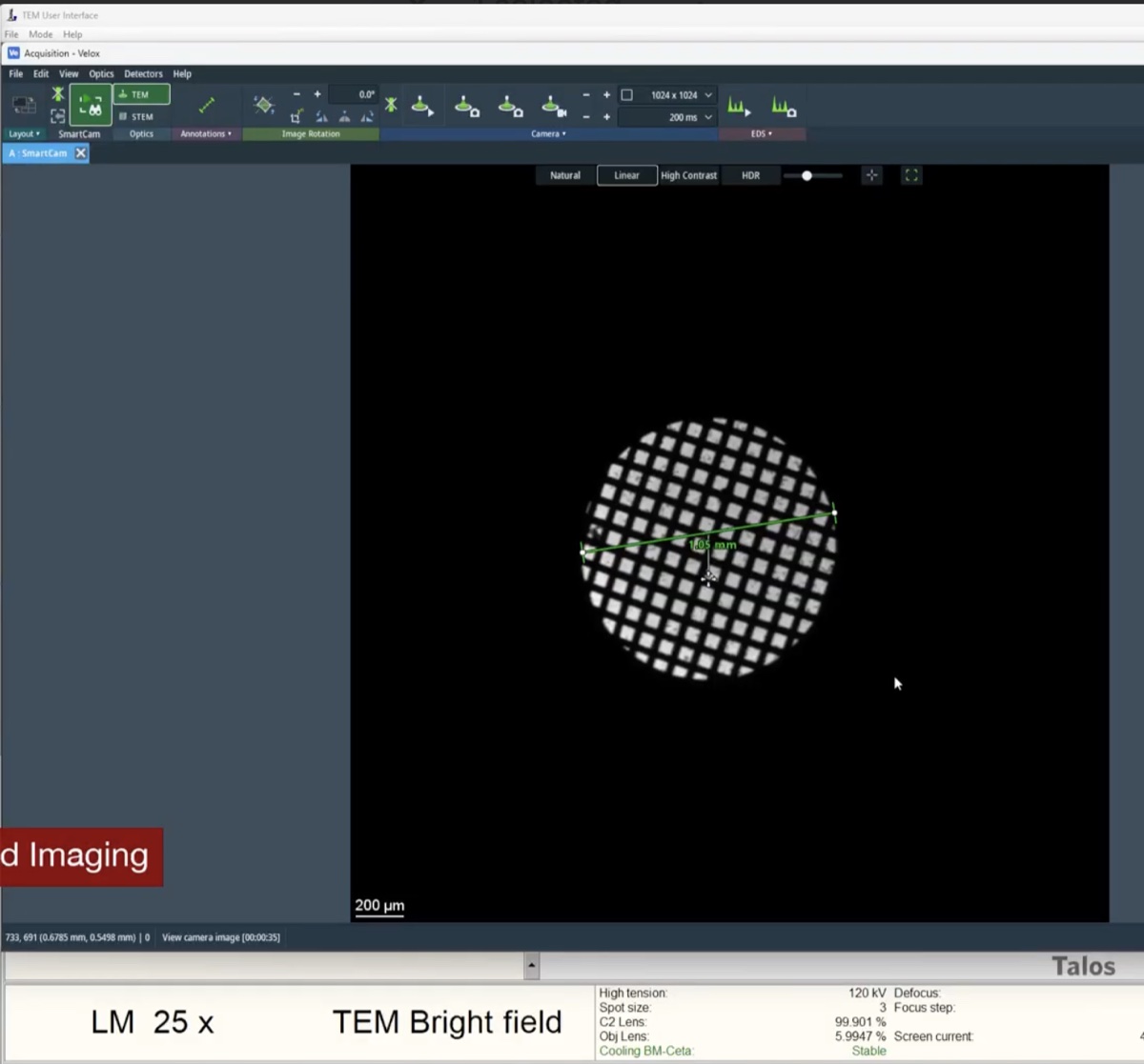
Navigate at ~25x magnification
-
Drop the magnification to roughly 25x using the magnification knob.
-
Move the stage to a feature of interest using the trackball.
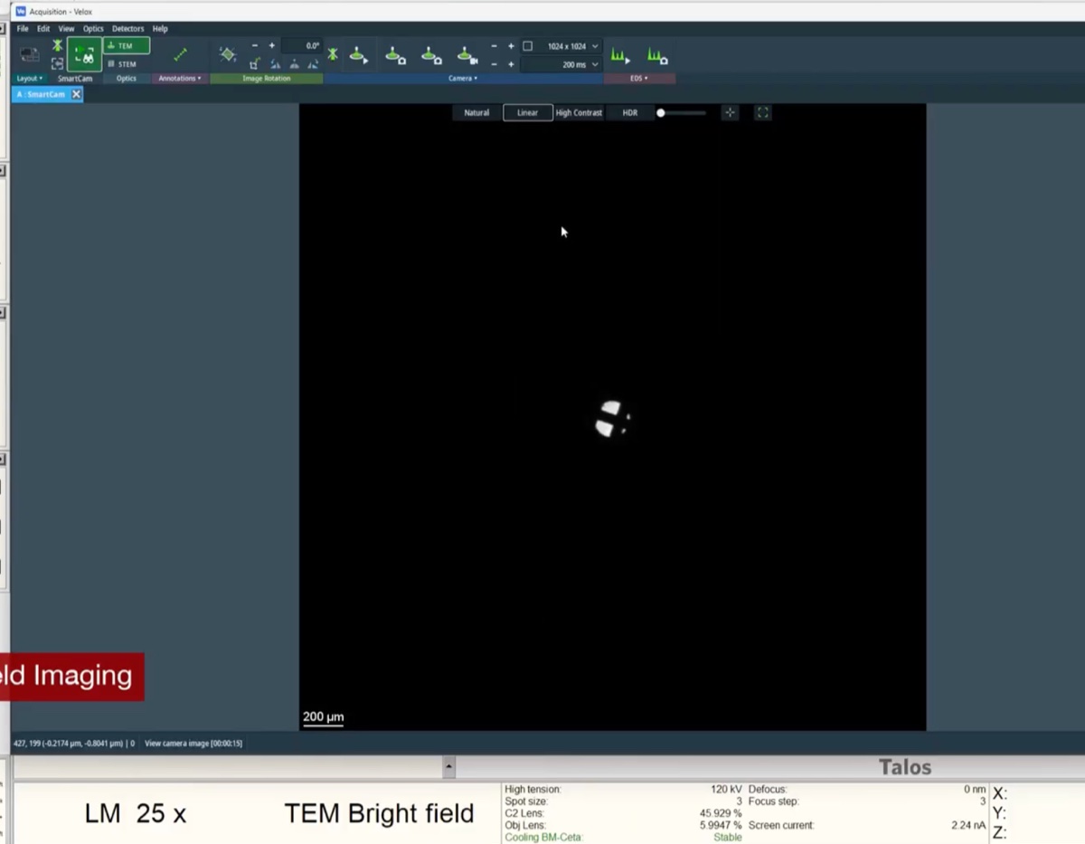
-
4.3 Set the illumination
-
Use the intensity knob to spread or condense the beam
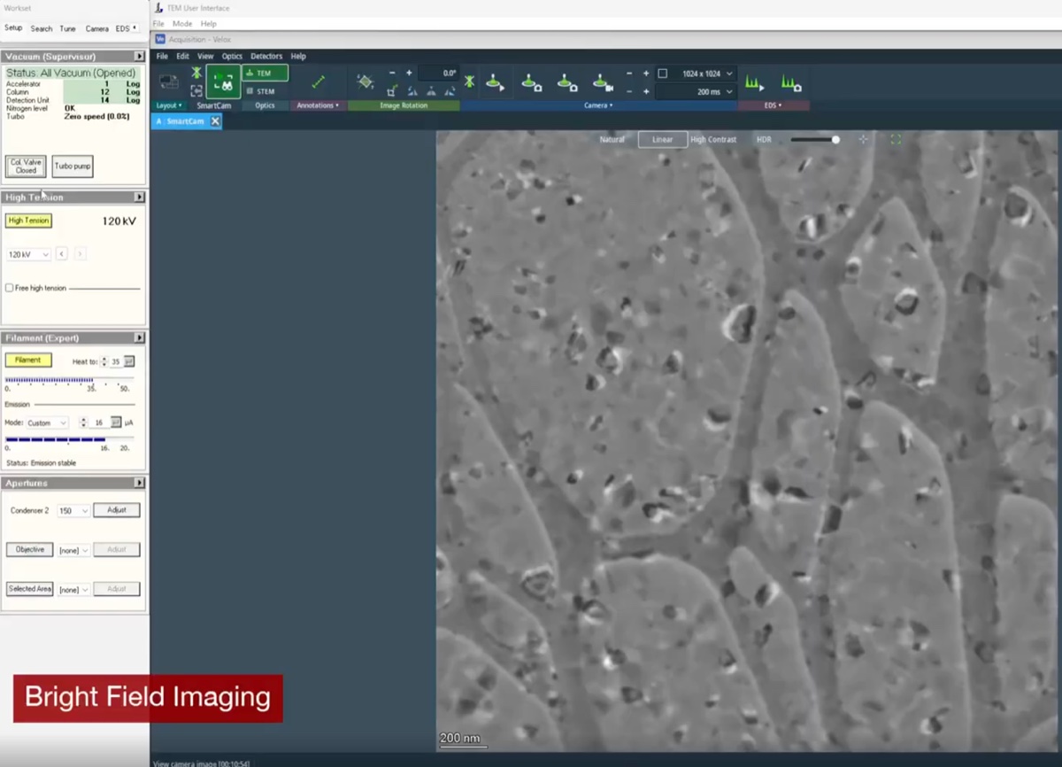
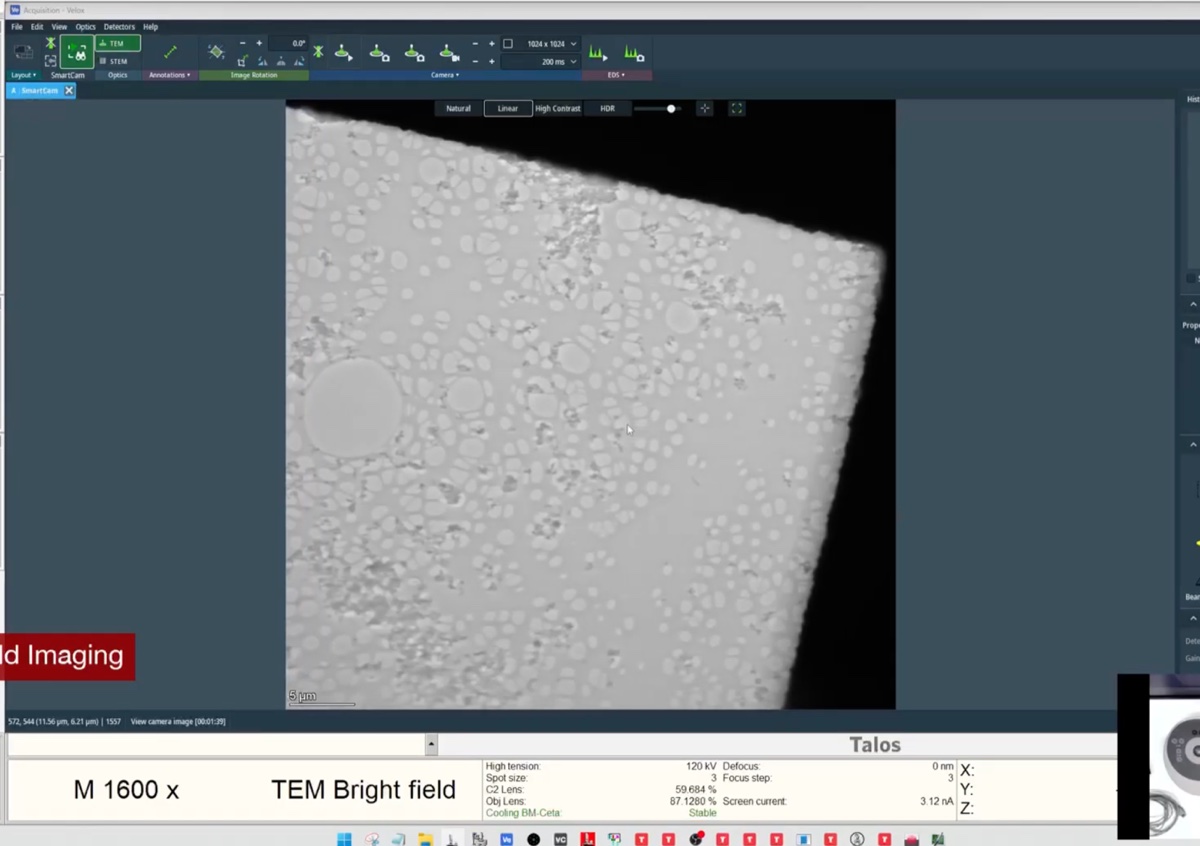
- Turn the intensity knob until the illumination on the sample is uniform and the histogram fills the dynamic range without saturating.
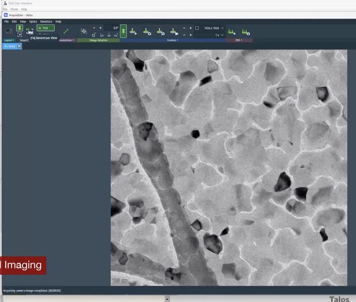
4.4 Acquire and annotate
-
Acquire and annotate a bright-field image
-
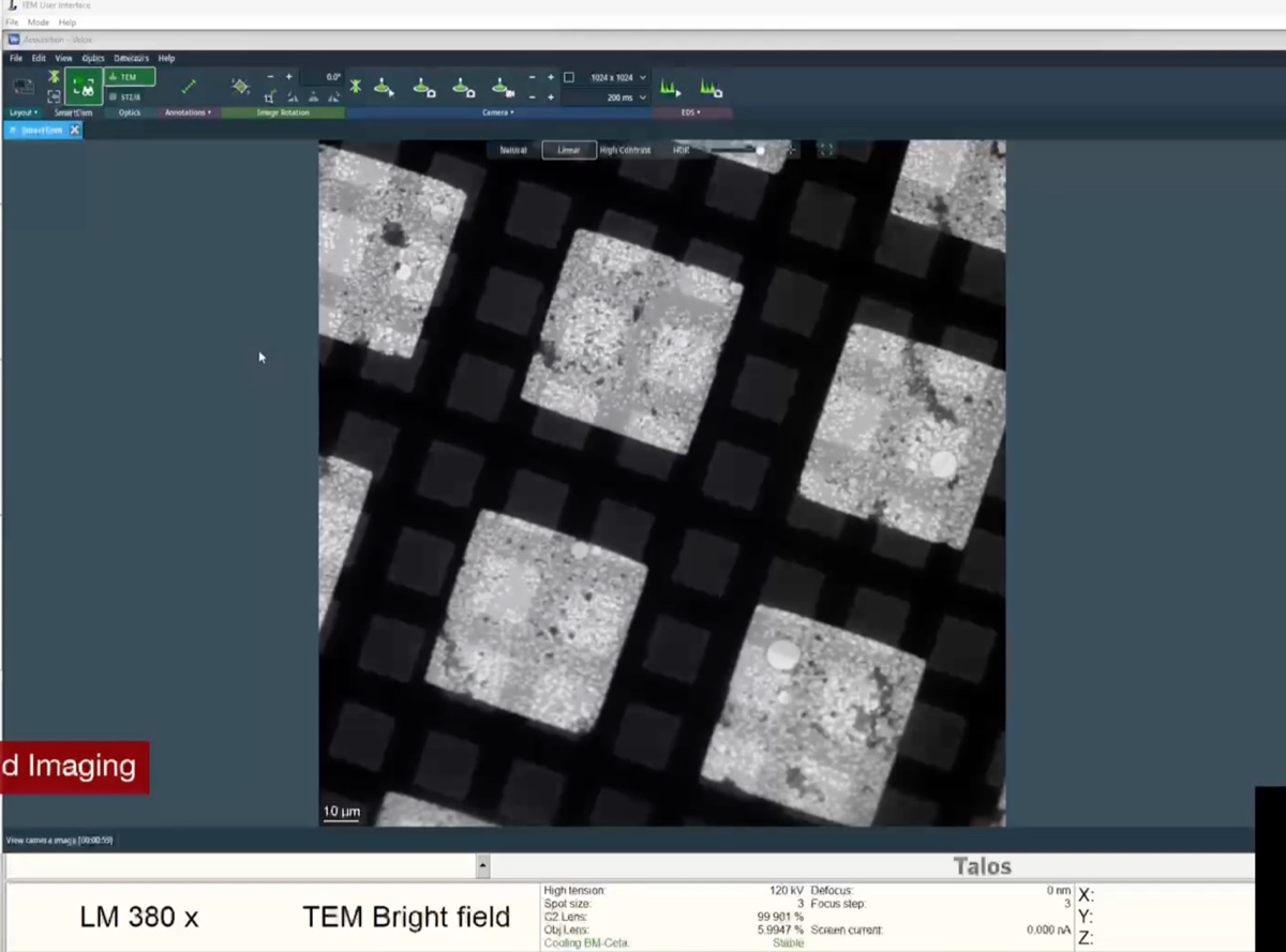
Acquire an image with the chosen camera.
-
Use the
Veloxannotation tool to label features, mark positions, or add scale annotations.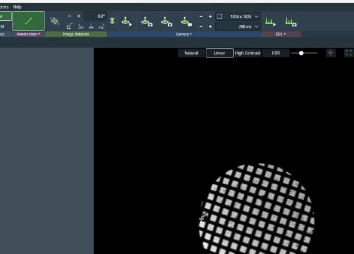
-
Part 5: Dark-field imaging
5.1 Switch the multi-function knob to beam tilt
-
Set mulXY to beam tilt mode
-
Switch the multi-function knob (
mulXY) so that it controls beam tilt rather than stage motion. Beam tilt is the mechanism used to align a chosen diffraction spot onto the optical axis for dark-field imaging.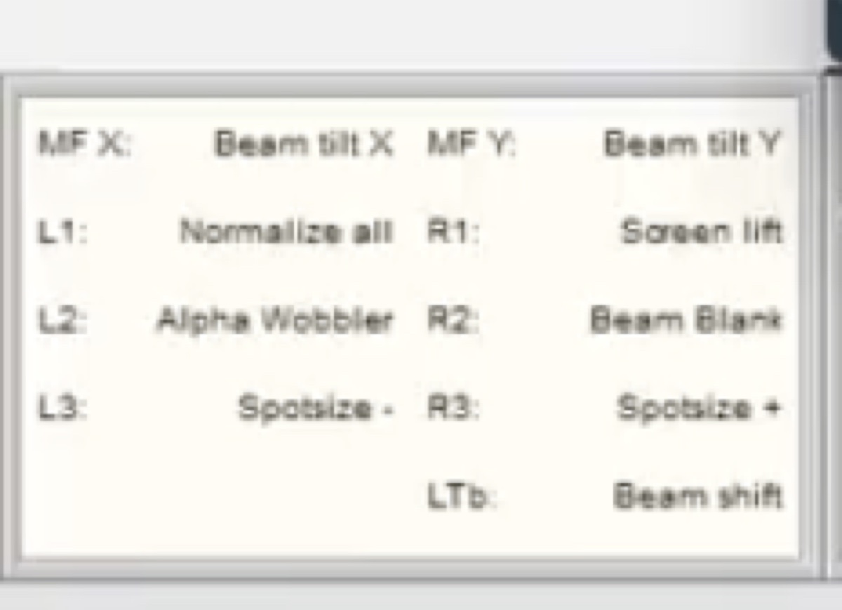
-
5.2 Enter dark-field mode
-
Press the dark-field button
-
Press the dark-field button on the hardware panel to enter dark-field mode.
-
5.3 Tilt the beam to align a diffraction spot
-
Align the chosen Bragg reflection onto the optical axis
-
Tilt the beam with the multi-function knob until the chosen diffraction spot sits on the optical axis. In diffraction mode, the central beam and the selected Bragg reflection swap positions when dark-field mode is toggled on.
-
5.4 Compare bright-field and dark-field images
-
Acquire matched BF and DF images of the same area
-
Acquire a bright-field reference image first.
-
Switch back into dark-field mode, leave diffraction mode, and retract the selected-area aperture.
-
Acquire the dark-field image.
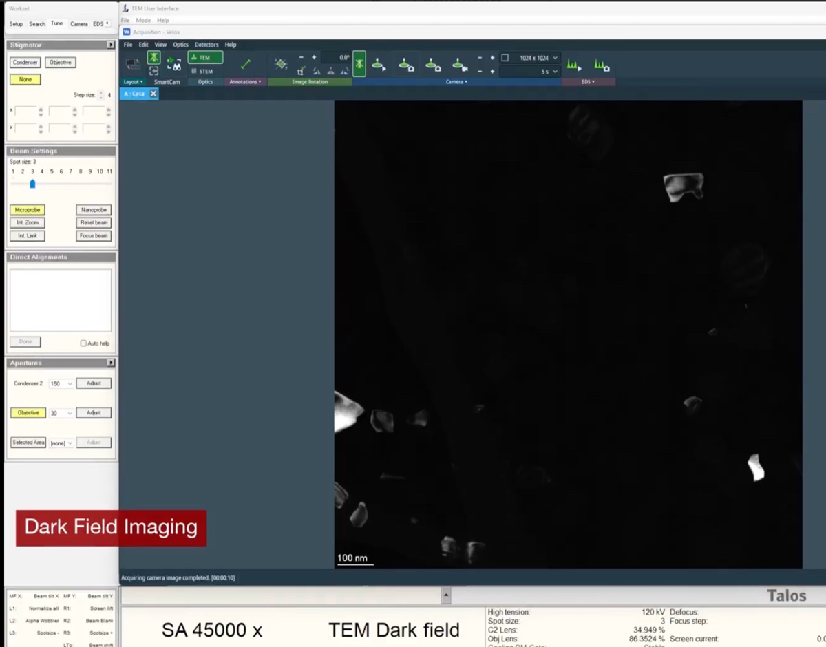
NOTE: Contrast is inverted between BF and DF: grains that diffracted strongly into the selected reflection now appear bright against a dark background.
-
Changelog
- May 11, 2026 : Moved the underfocus/overfocus reference into Session notes since it is session-specific rather than part of the general BF/DF procedure.
- May 11, 2026 : Initial draft compiled from the April 2026 Talos sessions by @bobleesj. BF and DF procedure structure adapted from the existing Phenom Pharos SOP layout.