TEM (Spectra)
This guide covers optional TEM alignment on the Spectra 300: column setup, eucentric height, aperture alignment, and image correction. TEM mode is useful for fast sample navigation and for users who need TEM-specific data (HRTEM, diffraction patterns). Most users will proceed directly to STEM (Spectra).
Prerequisite: The sample is already loaded and the holder is inserted into the Spectra 300. For sample loading and end session procedures, see STEM (Spectra).
Acronyms:
mulXY- Multifunction X/Y knobs on hand panelTEMUI- TEM User Interface (software)
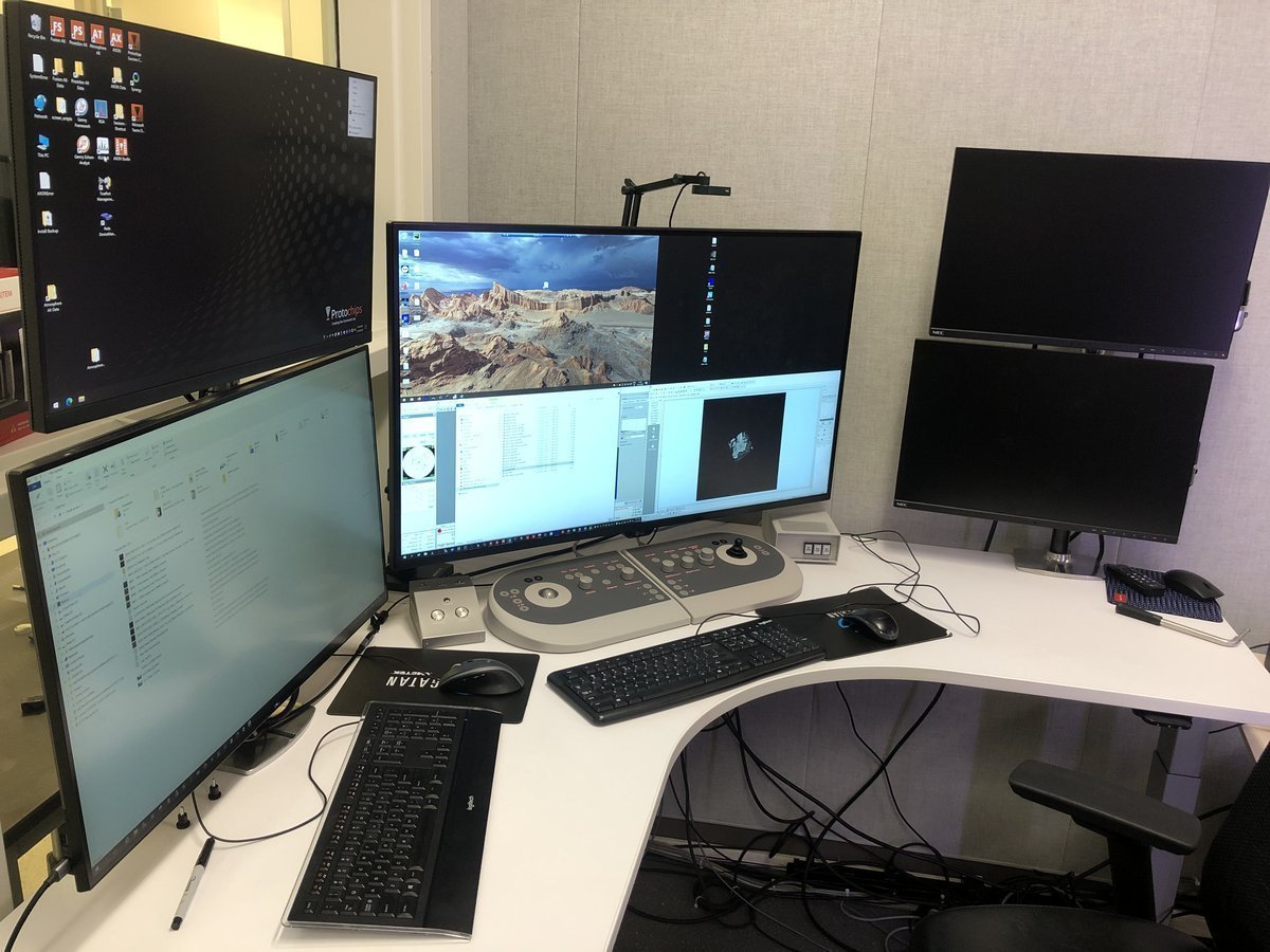
Workstation layout:
| Monitor | Software | Purpose |
|---|---|---|
| Bottom left | TEMUI | Microscope control, vacuum, alignments |
| Bottom right | Velox | Live imaging, acquisition |
| Top left | ImageCorrector | Aberration measurement & correction |
| Top right | Velox image gallery | Captured images from Velox |
Overview
This guide covers two main phases:
| Phase | Procedures | Time |
|---|---|---|
| Part 1: Column alignment | Vacuum check, beam setup, eucentric height, monochromator, C2 aperture, condenser stigmatism, beam tilt, rotation center | 10-15 min |
| Part 2: Image correction | Capture image, C1A1 correction, Tableau measurement, save settings | 10-15 min |
Part 0: Safety check
Complete the pre-session checklist in STEM (Spectra) before proceeding. Do not skip this step.
Part 1: Column alignment
1.1 Open column valves
Before imaging, verify that the vacuum system is ready and the column valves can be safely opened.
-
Verify vacuum pressure
-
In
TEMUI, check the vacuum pressure values on the log scale (lower = better):Gauge Log Value Why Important Gun 1 Highest vacuum needed for stable electron emission Liner <10 Prevents electron scattering along beam path Octagon 1 Protects sample from contamination and oxidation Projection <30 Maintains image quality in projection system Buffer tank <50 Ensures stable pumping performance Backing line <80 Turbo pump pushes compressed gas into the backing line
-
-
Open column valves
-
In
TEMUI, clickCol Valves Open. The status changes to indicate the column valves are open and the turbo pump is off.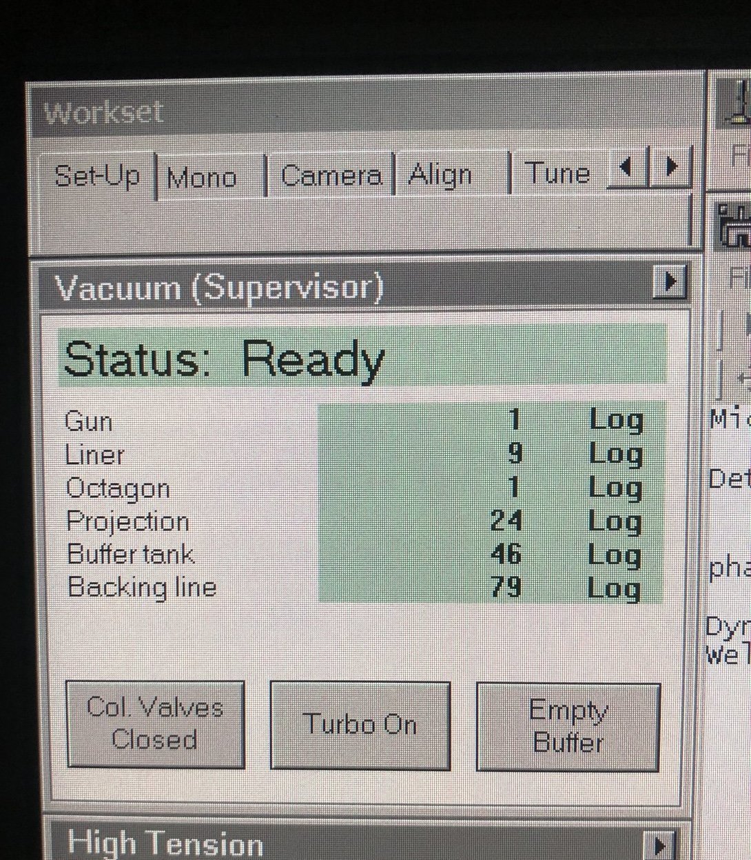
-
-
Set condenser apertures
-
In
TEMUI, go to theTunetab, thenApertures. Set Condenser 1, 2, 3 to 2000, 70, 1000.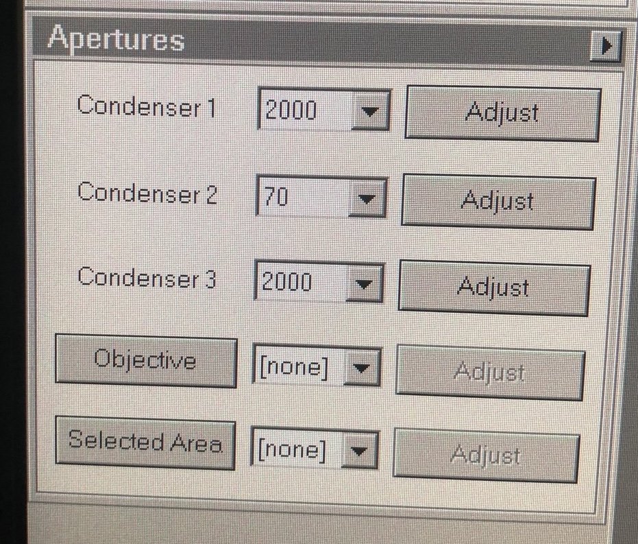
-
1.2 Beam setup
Configure the beam parameters for initial navigation and sample finding.
-
Enter TEM mode
- On the
Veloxsoftware (bottom right monitor), verify TEM mode is active. If not, click theTEMbutton.
- On the
-
Set spot size
- Set Spot Size 3 by pressing the
L3orR3button on the hand panel. As spot size decreases, screen current increases and the image gets brighter. - If the image is too bright, turn the intensity knob to decrease the screen current to around 2 nA and press
Linearmode to see better contrast.
- Set Spot Size 3 by pressing the
-
Find sample region
-
Set ~500x magnification by adjusting the magnification knob.
-
Locate the gold (dark) and amorphous carbon boundary by driving the joystick on the hand panel. This contrast boundary serves as a visual marker to identify the region of interest across various magnifications.
-
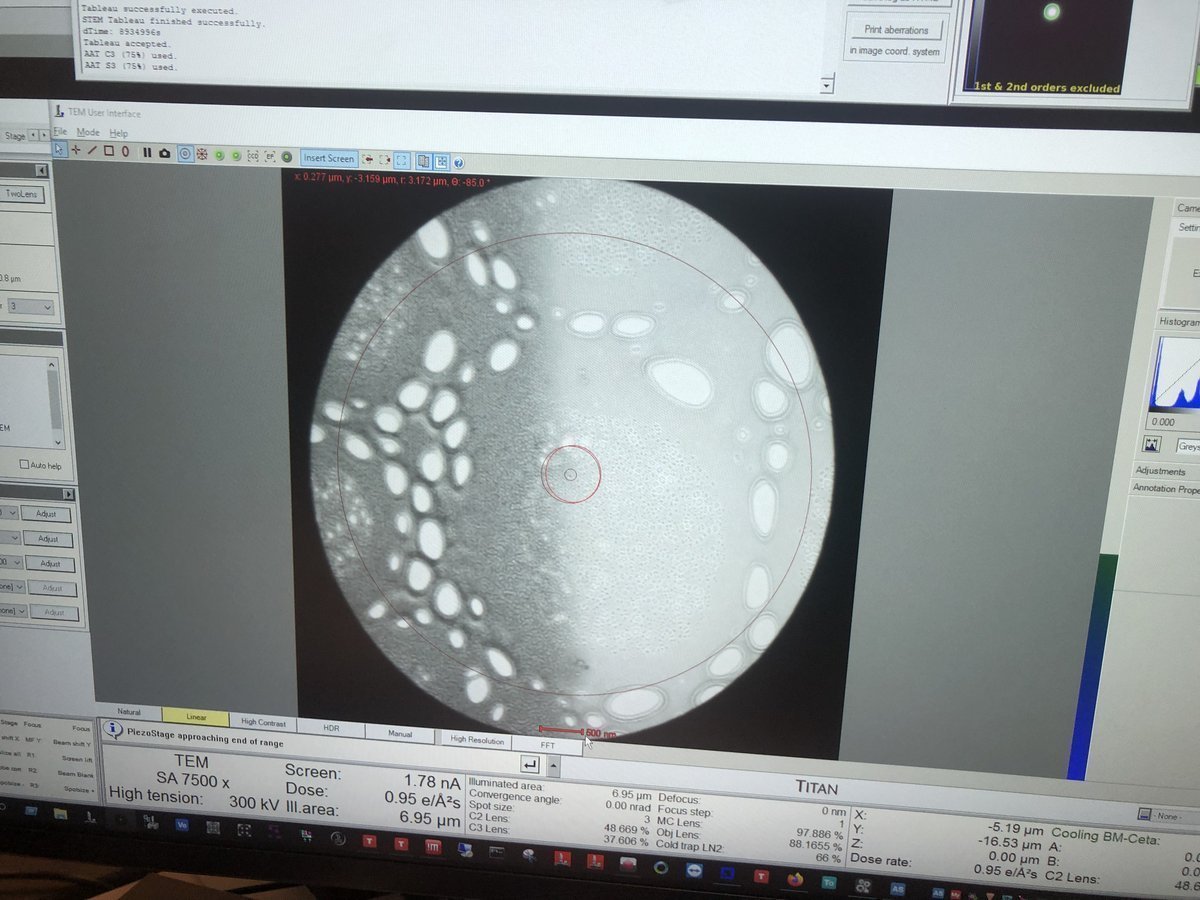
1.3 Eucentric height
At eucentric height, the sample remains stationary when tilted. This is essential for accurate imaging and aberration correction. Complete eucentric height alignment after loading each sample. Do not skip this step.
-
Adjust z-axis
-
Set ~7,500x magnification by adjusting the magnification knob.
-
Press
z-axisup or down on the hand panel. Watch the image contrast change as the sample moves through focus. At eucentric height, the contrast is minimized (the image appears most “washed out”).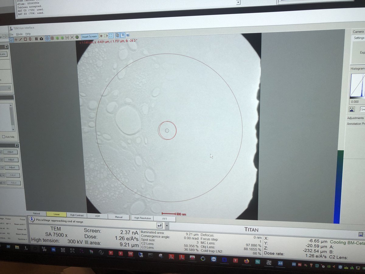
-
1.4 Monochromator tune
The monochromator selects a narrow energy range from the electron beam. If the beam edge looks jagged, the monochromator needs alignment.
-
Check beam edge
- Do you see a jagged area along the beam edge in the previous step? If not, skip this section. Otherwise, follow the steps below.
-
Adjust monochromator
-
In
TEMUI, go to theMonotab, then openMonochromator Tune (Expert)and clickShift.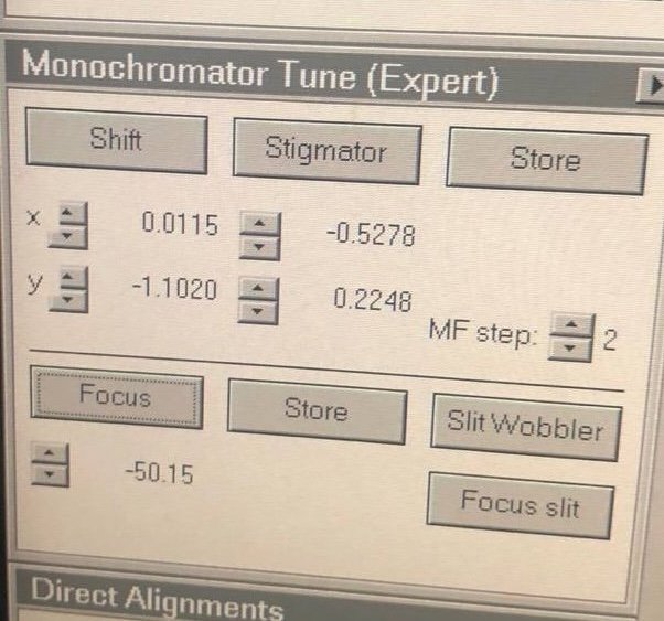
-
Adjust
mulXYknobs until the jagged area disappears.
-
1.5 C2 aperture alignment
The C2 aperture controls convergence angle and beam size. It blocks off-axis electrons — only electrons within a certain angular range pass through. A user must center this aperture on the optical axis so that the beam expands and contracts symmetrically.
-
Enter two-lens mode
-
In
TEMUI, go to theTunetab, thenBeam Settings, and clickTwolens. In two-lens mode, C3 is turned off, so the beam behavior on screen is purely from C2. This makes it straightforward to detect and correct any C2 aperture misalignment. In three-lens mode, C3 reshapes the beam after C2, masking the misalignment.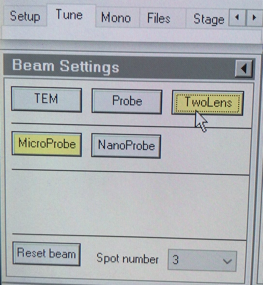
-
-
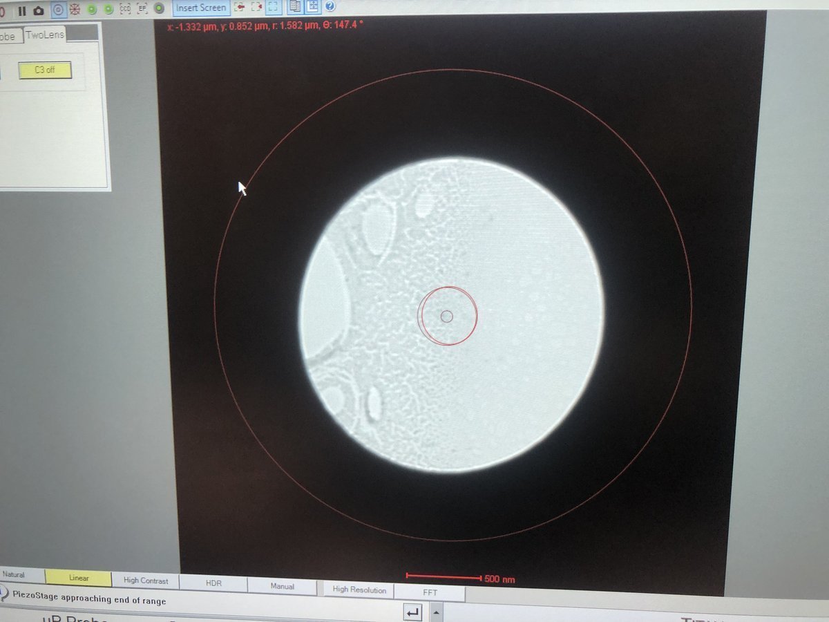
Center and align C2 aperture
-
Center the beam by rolling the hand panel ball.
-
Converge the beam by varying the intensity knob.
-
Vary beam size by turning the intensity knob counterclockwise and clockwise. Notice the beam expansion is not concentric — this indicates the C2 aperture is off-center.
-
Make the beam concentric: go to
Apertures, clickAdjustnext toCondenser 2, then adjust themulXYknobs until the beam expands and contracts concentrically.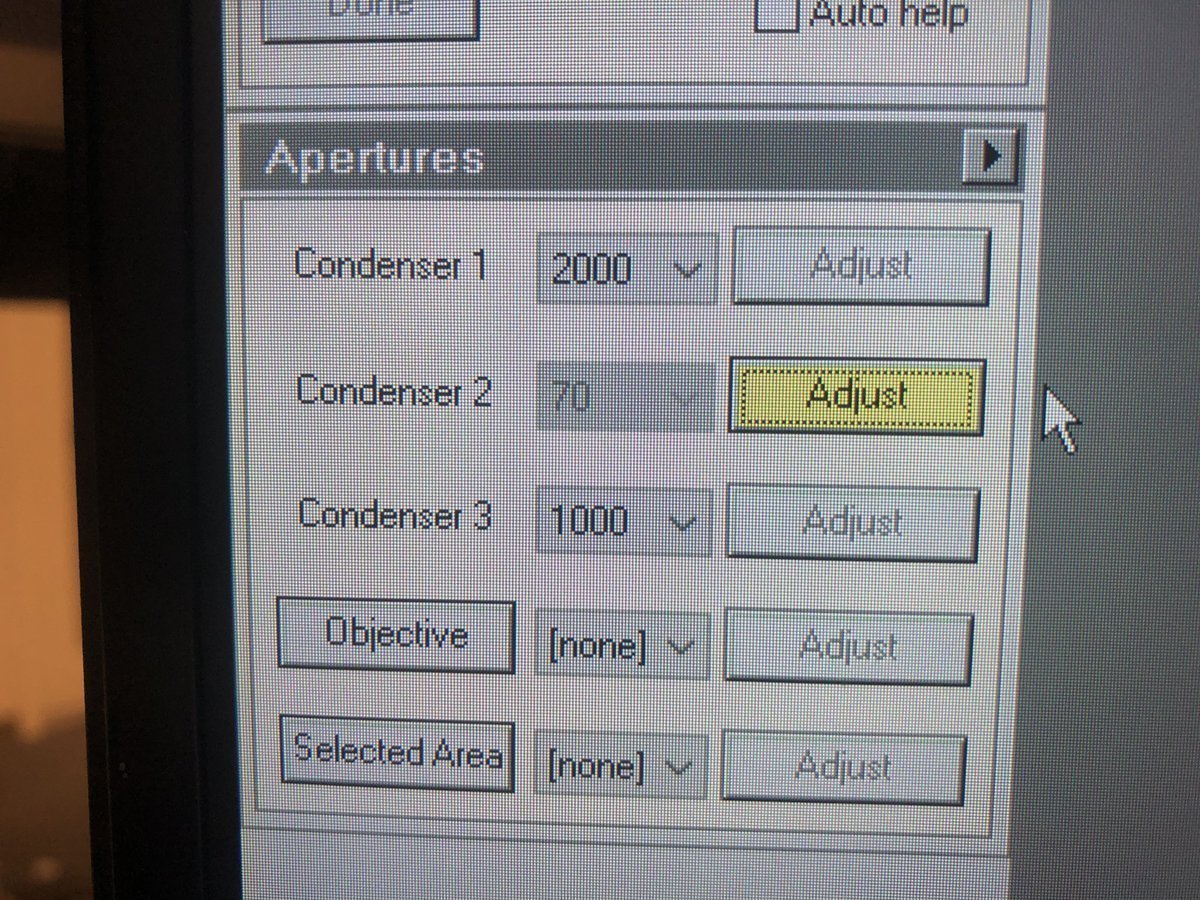
-
-
Return to three-lens mode
-
In
TEMUI, go toBeam Settingsand clickTEMto return to three-lens mode.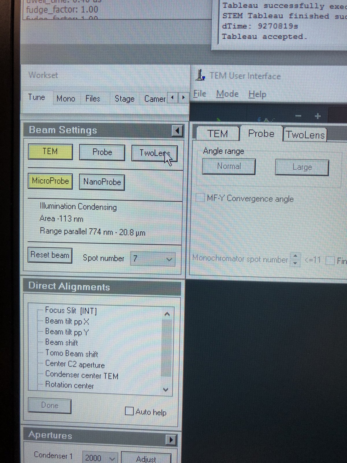
-
Verify the beam is centered and concentric.
-
1.6 Condenser stigmatism
Condenser astigmatism causes the beam to appear elliptical instead of round. Correcting this ensures a symmetric probe.
-
Increase magnification
- Set ~200kx magnification by adjusting the magnification knob.
- If the beam has shifted from center, go to
Tunetab, thenDirect Alignment, clickBeam Shift, and adjust themulXYknobs to re-center.
-
Correct stigmatism
-
Enlarge the beam by adjusting the intensity knob.
-
In
TEMUI, clickStigmator, thenCondenser. Adjust themulXYknobs to make the beam as round as possible. The beam should remain circular as you vary the intensity knob. PressNonewhen done.
-
1.7 Beam tilt
Beam tilt alignment minimizes lateral beam shift when the beam angle changes. Proper alignment ensures the beam tilts around a single point without drifting.
-
Align beam tilt
- In
TEMUI, go toDirect Alignmentand clickBeam tilt pp X. Adjust themulXYknobs to minimize the lateral jiggle. - Repeat for
Beam tilt pp Y. - If the beam center has shifted, click
Beam Shiftand adjust themulXYknobs to re-center.
- In
1.8 Rotation center
Rotation center alignment ensures the image rotates around the center of the field of view when focus changes.
-
Align rotation center
- In
TEMUI, go toDirect Alignmentand clickRotation Center. The image pulses in and out of focus. - Adjust the
mulXYknobs to minimize lateral movement. The pulsing should appear concentric (expanding and contracting from the same point) with no side-to-side drift.
- In
Part 2: Image correction
2.1 Capture image
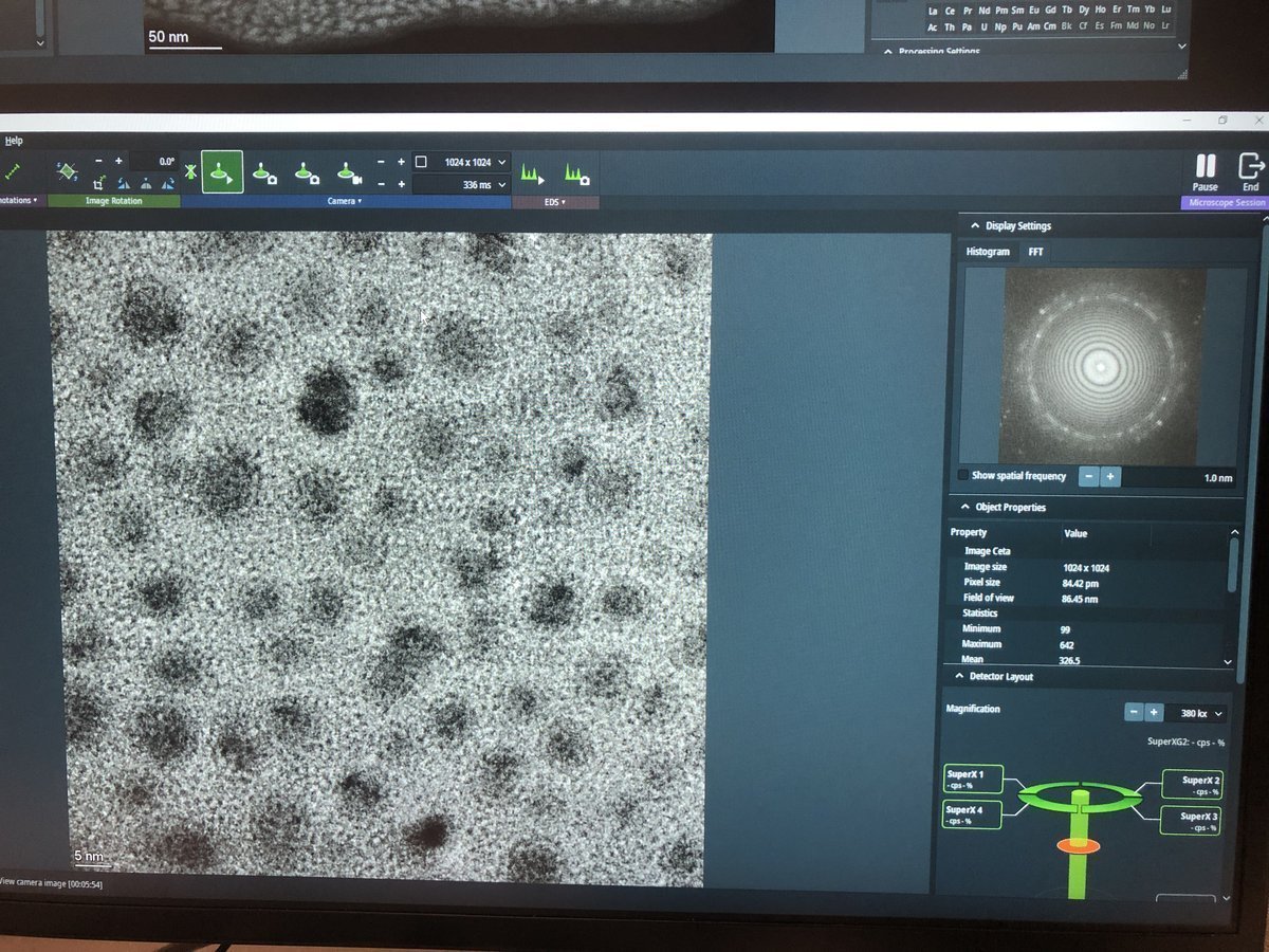
Before running the image corrector, a user must set up live imaging in Velox and find a suitable sample region.
-
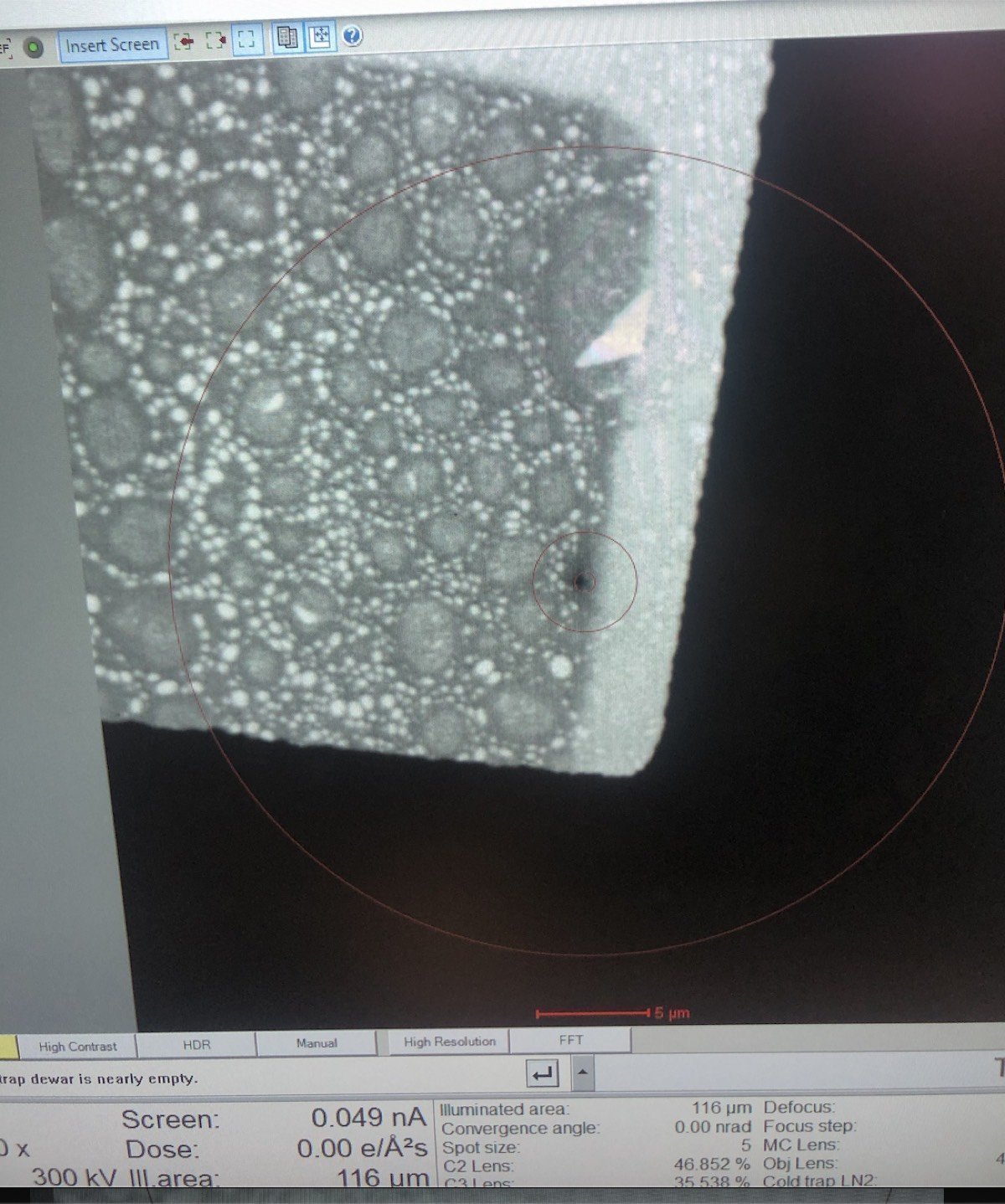
Prepare for imaging
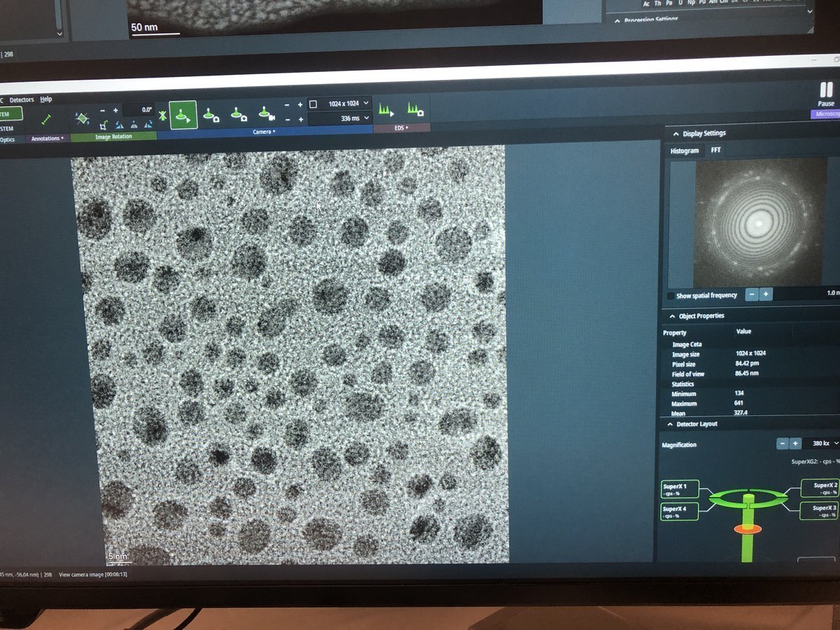
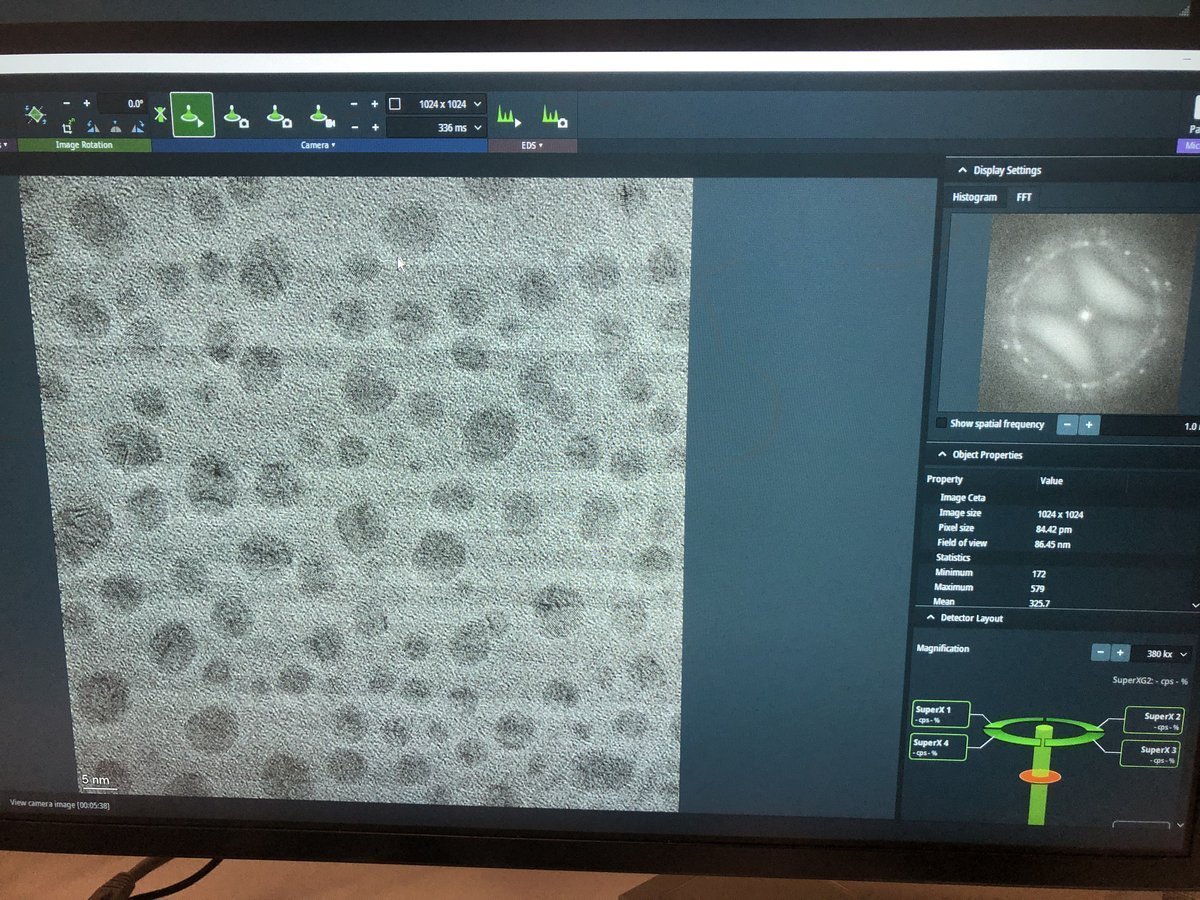
- Find a flat area with a distribution of particle sizes and no holes.
- Important: Enlarge the beam to cover the entire fluorescent screen before lifting it. When the screen is raised, the camera and detectors below are exposed to the beam. A concentrated beam can permanently damage them.
- Press
R1on the hand panel to lift the fluorescent screen.
-
Start live imaging
-
In
Velox(right monitor), click the play button to start live imaging.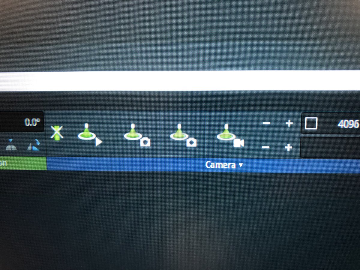
-
Do not change the intensity knob while the screen is lifted. The screen is lifted when
TEMUIshows a black display with dose reading “Unavail”. -
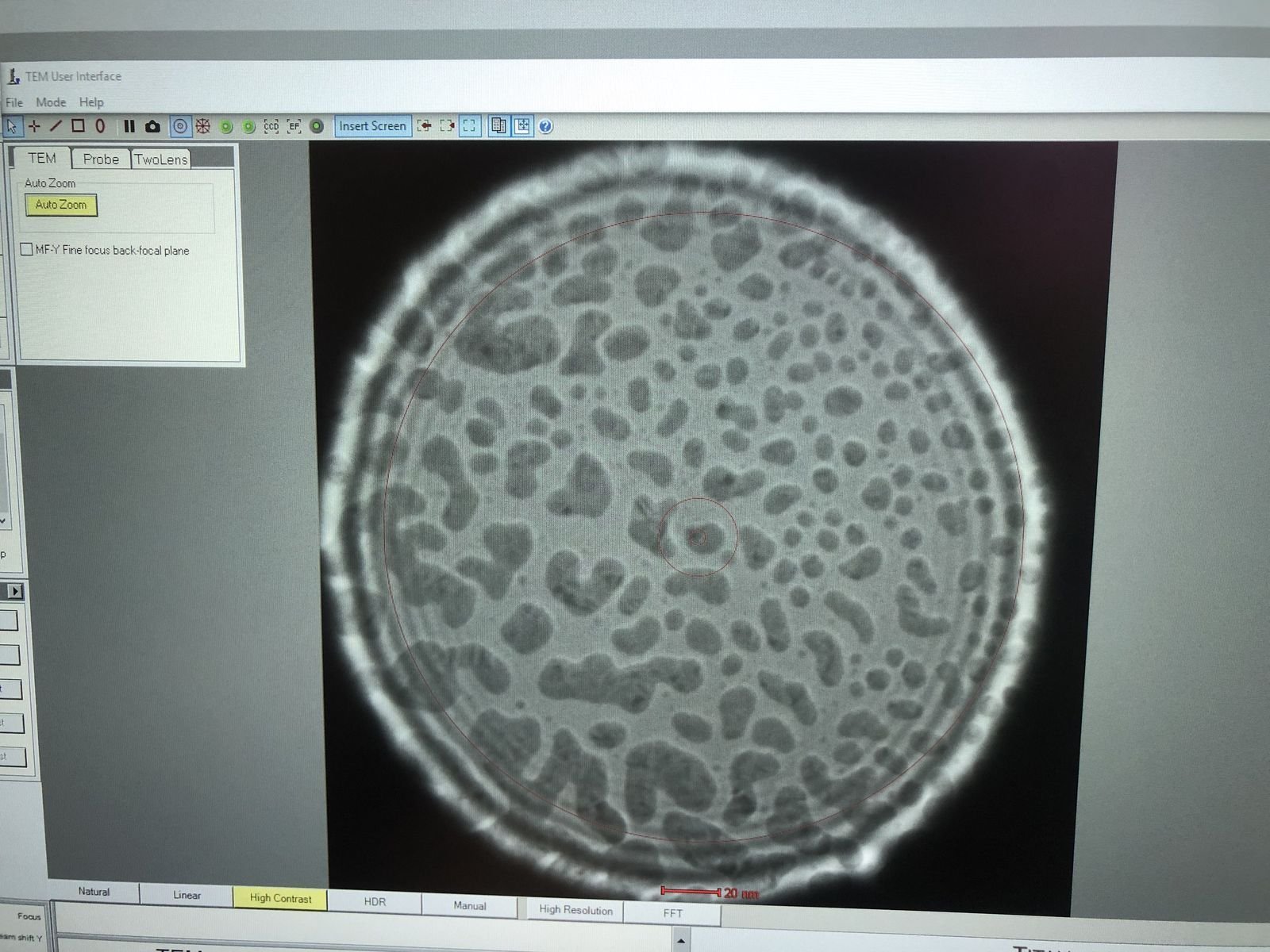
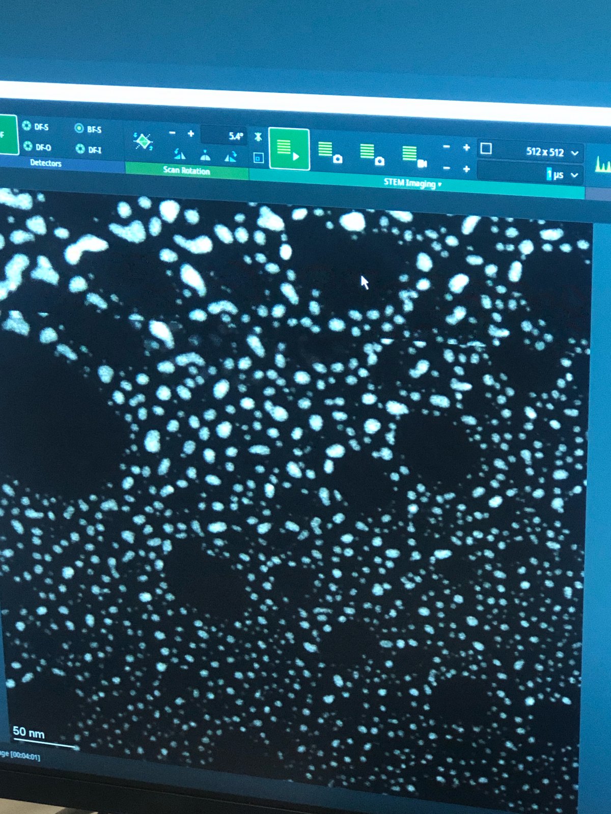
Gold nanoparticles should be visible on screen.
-
-
Explore focus (optional)
-
Press the
z-axisbuttons to observe how focus affects the image.Underfocus — edges appear bright with white Fresnel fringes:
On focus — minimal fringe contrast:
Overfocus — contrast inverts, dark fringes at edges:
-
2.2 C1A1 correction
C1A1 corrects first-order aberrations in the image-forming lenses: defocus (C1) and 2-fold astigmatism (A1).
-
Set underfocus
-
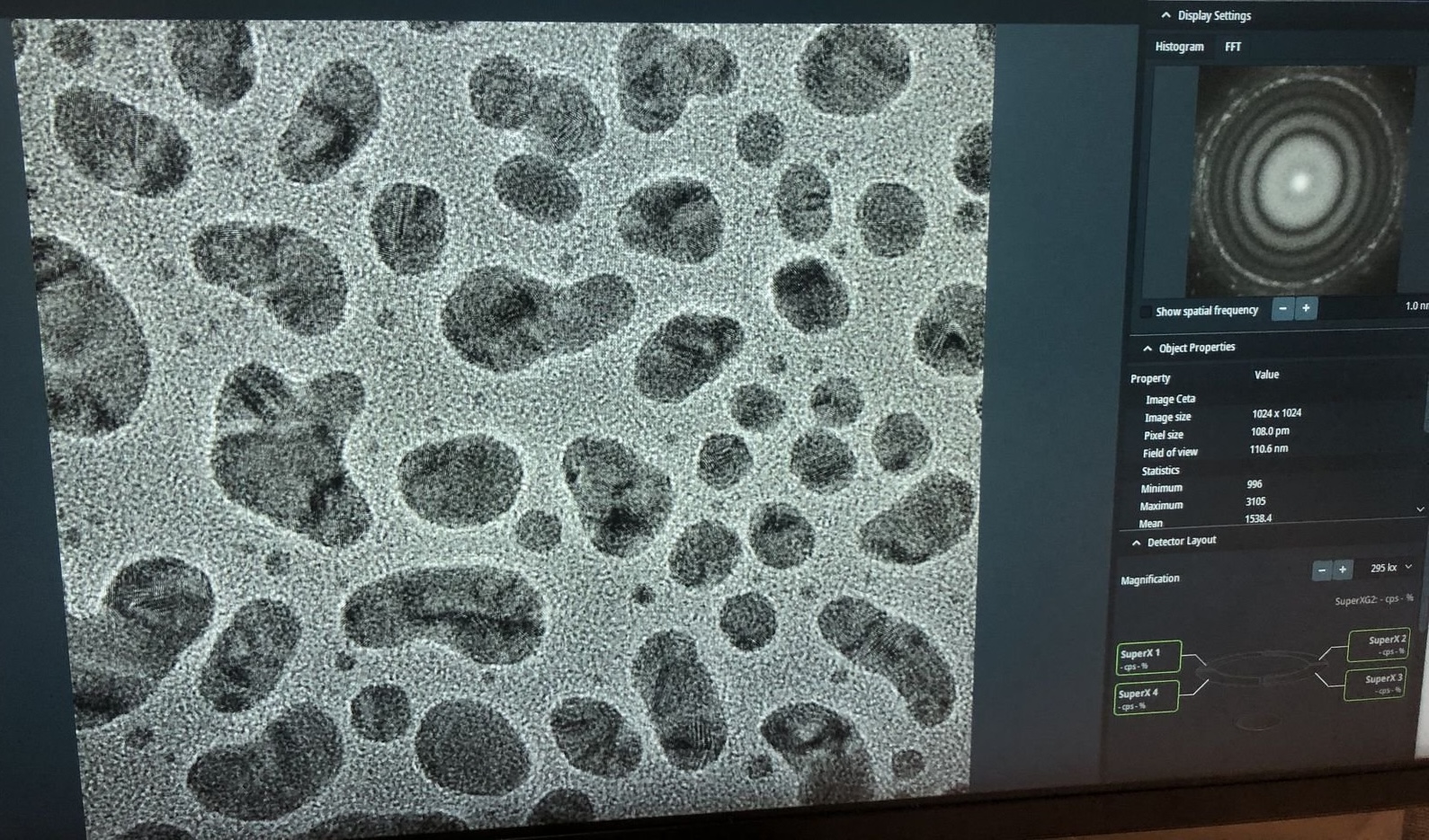
Press
Z-axisdown until you see 4-5 rings in the FFT (slight underfocus). The rings indicate Thon rings from the amorphous carbon, which the corrector software uses for aberration measurement.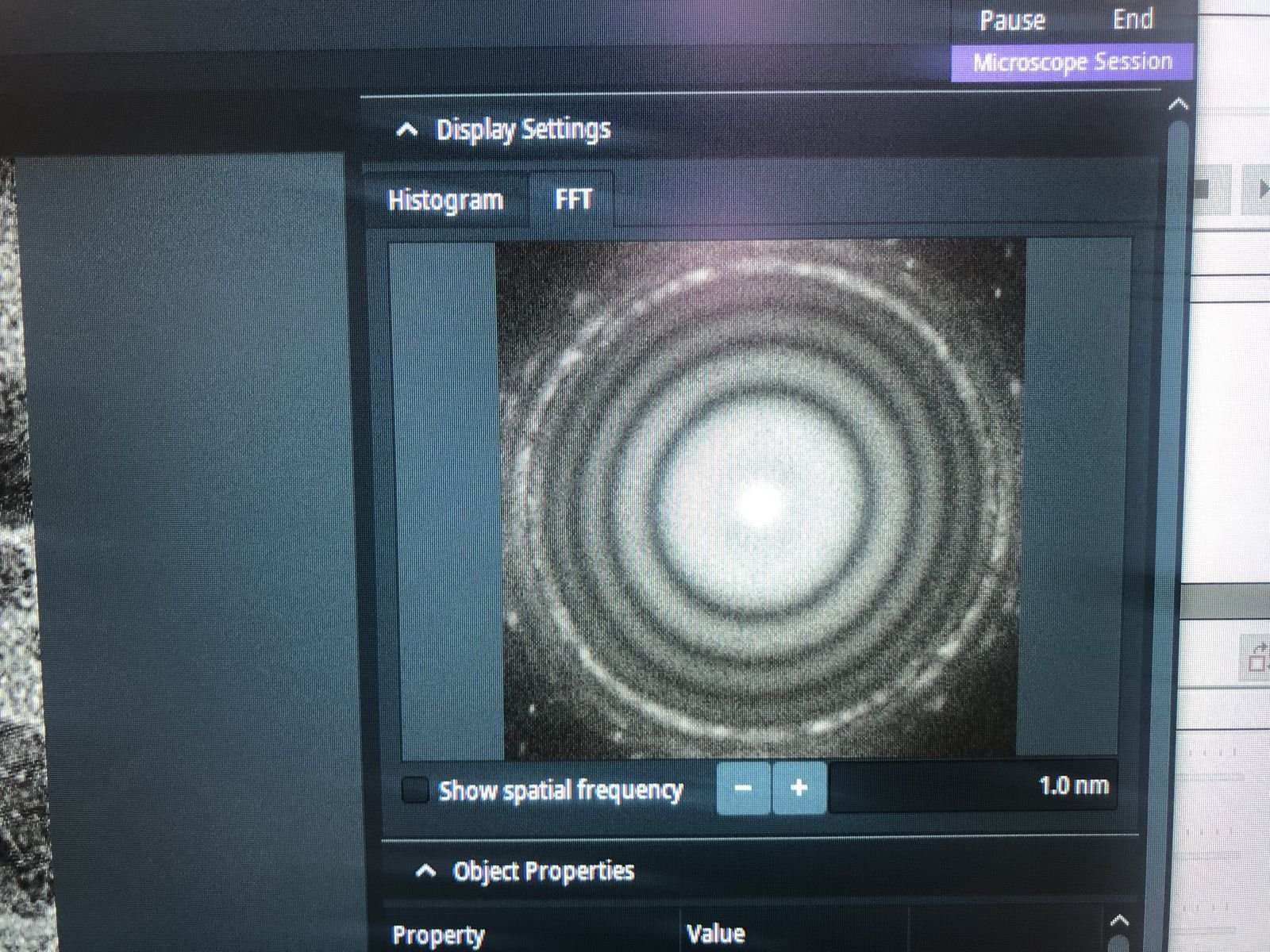
-
-
Reset stigmator values
-
Stop live scanning by clicking the play button in
Velox. -
In
TEMUI, go to theStigmatorquick tab. ResetObjectiveandImage A1to zero. If non-zero, right-click each button to reset, then clickDone.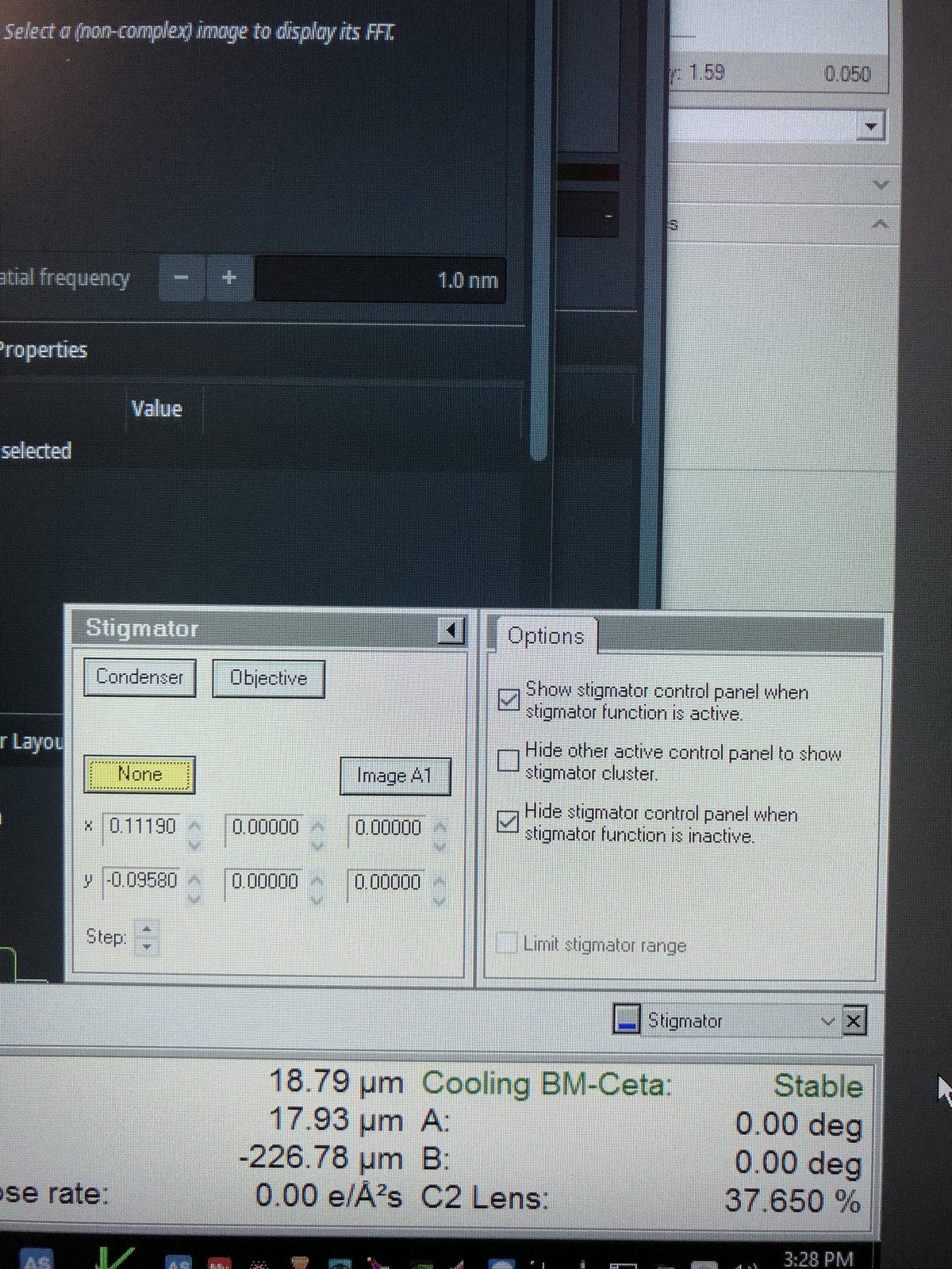
-
-
Run C1A1
-
Open the
ImageCorrectorsoftware (top left monitor). -
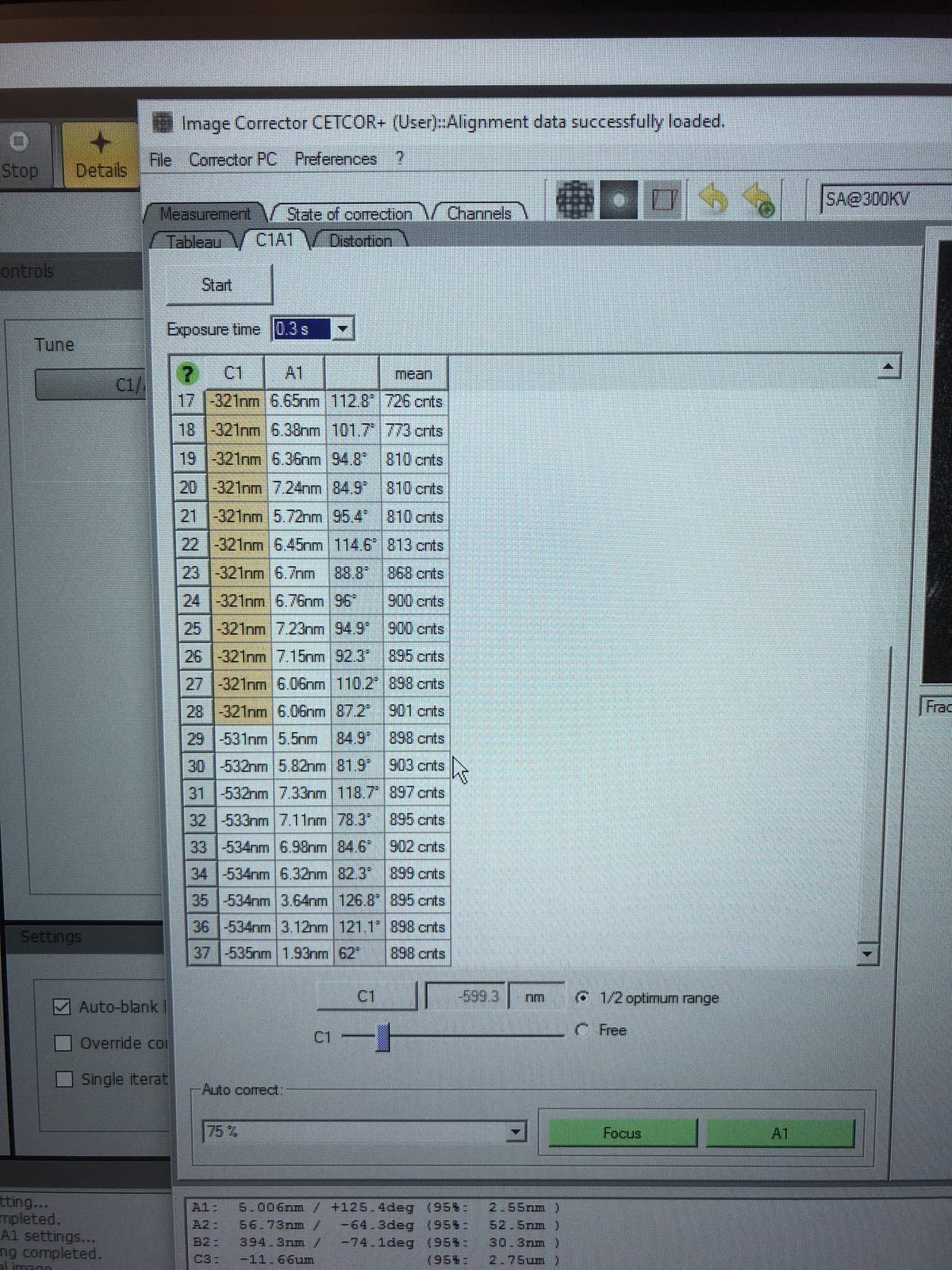
Set exposure time to 0.3s.
-
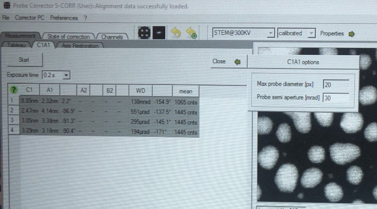
Go to the
C1A1tab and clickStart. The microscope wobbles the focus up and down (changing objective lens current). The FFT is captured and its ring symmetry, angular distribution, and ring spacing are analyzed. -
During the iteration, carefully set intensity to 800–900 counts by adjusting the intensity knob so the corrector has enough signal.
-
Under
Auto correct, set to75%, then pressFocusandA1during the iteration to apply corrections. -
Aim for
A1< 5 nm. IfC1shows orange, manually adjust the Z-axis during the iteration.C1should be close to the suggested value (in the image above, the software suggests C1 of −599.3 nm).
-
2.3 Tableau measurement
Tableau measures higher-order aberrations by acquiring images at multiple beam tilts. This is necessary for sub-angstrom resolution.
-
Run Tableau
-
In
ImageCorrector, go to theTableautab, selectStandardnext toTableau type, then clickStart.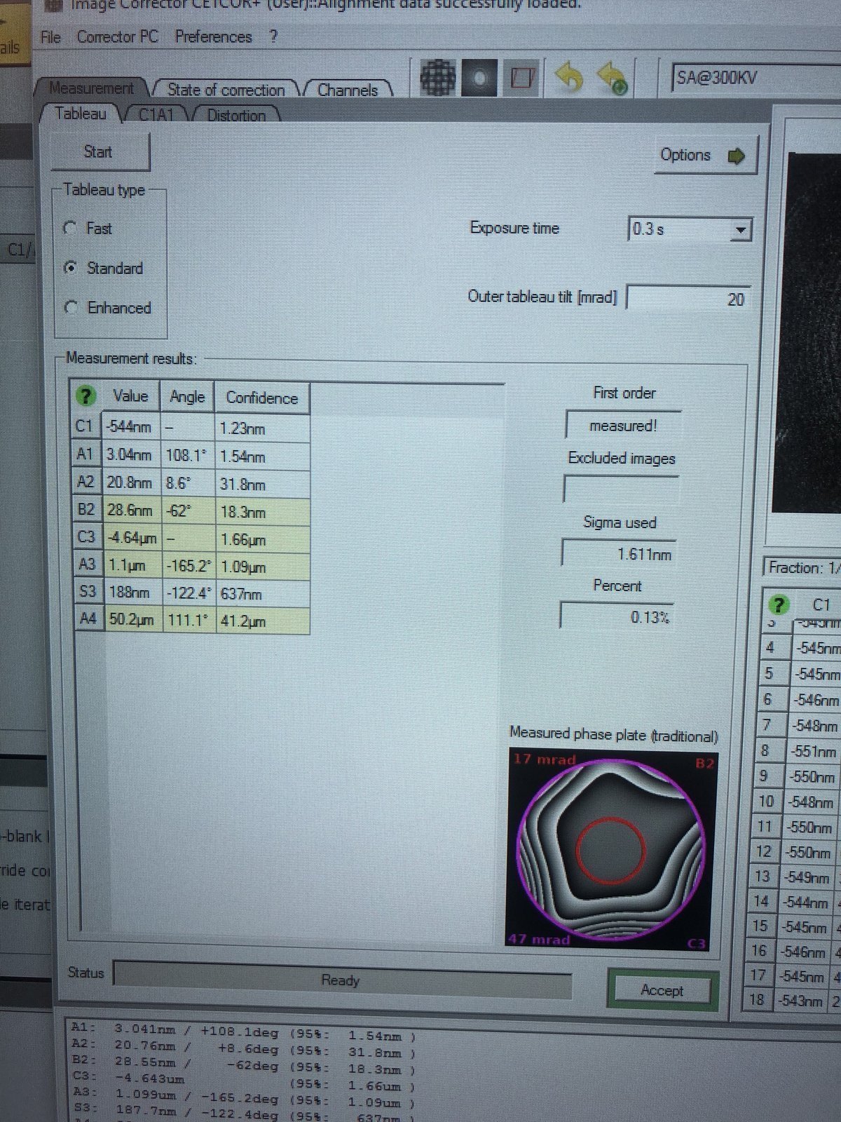
-
-
Verify results
-
After the iteration completes, verify the aberration values match the targets below, then click
Accept:Parameter Resolution < 0.10 nm (20 mrad) Resolution < 0.08 nm (24 mrad) A1 < 5 nm < 5 nm A2 < 100 nm < 50 nm B2 < 100 nm < 50 nm C3 ~ −8 μm ~ −8 μm A3 < 5 μm < 1.5 μm S3 < 5 μm < 1 μm -
In
Velox, click the camera button to capture an image and verify improvements.
-
2.4 Save optics settings
-
Save register
-
In
TEMUI, go toFiles, thenSBL FEG Registers. -
Add name
300KV-TEM-<NAME>and clickAdd.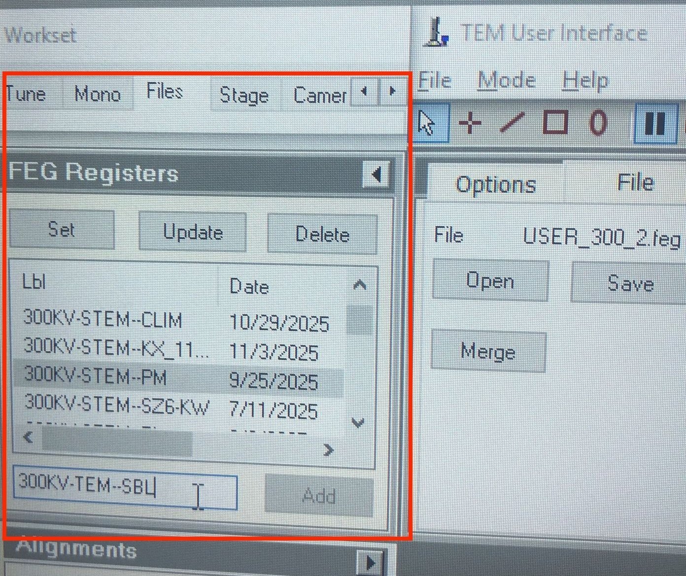
-
-
Verify corrected image
- In
Velox, click thePlaybutton to start live imaging and verify the aberration-corrected image quality. - Done. You are now ready for STEM probe alignment.
- In
Appendix
Reference images (click to expand)
Gray colors during C1A1 probe correction:
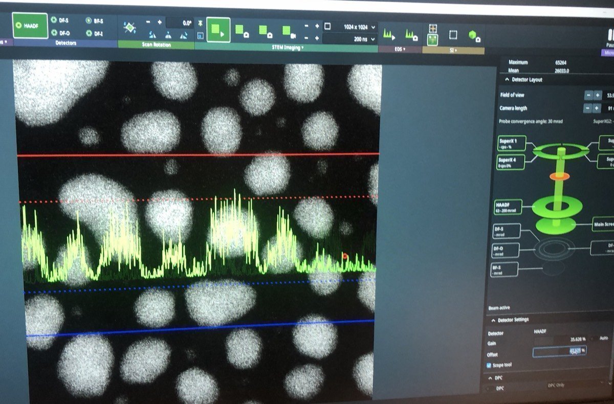
Seeing gray colors like below?
In Velox, click Auto-tune. Increase the signal until it touches the red and blue dotted lines:
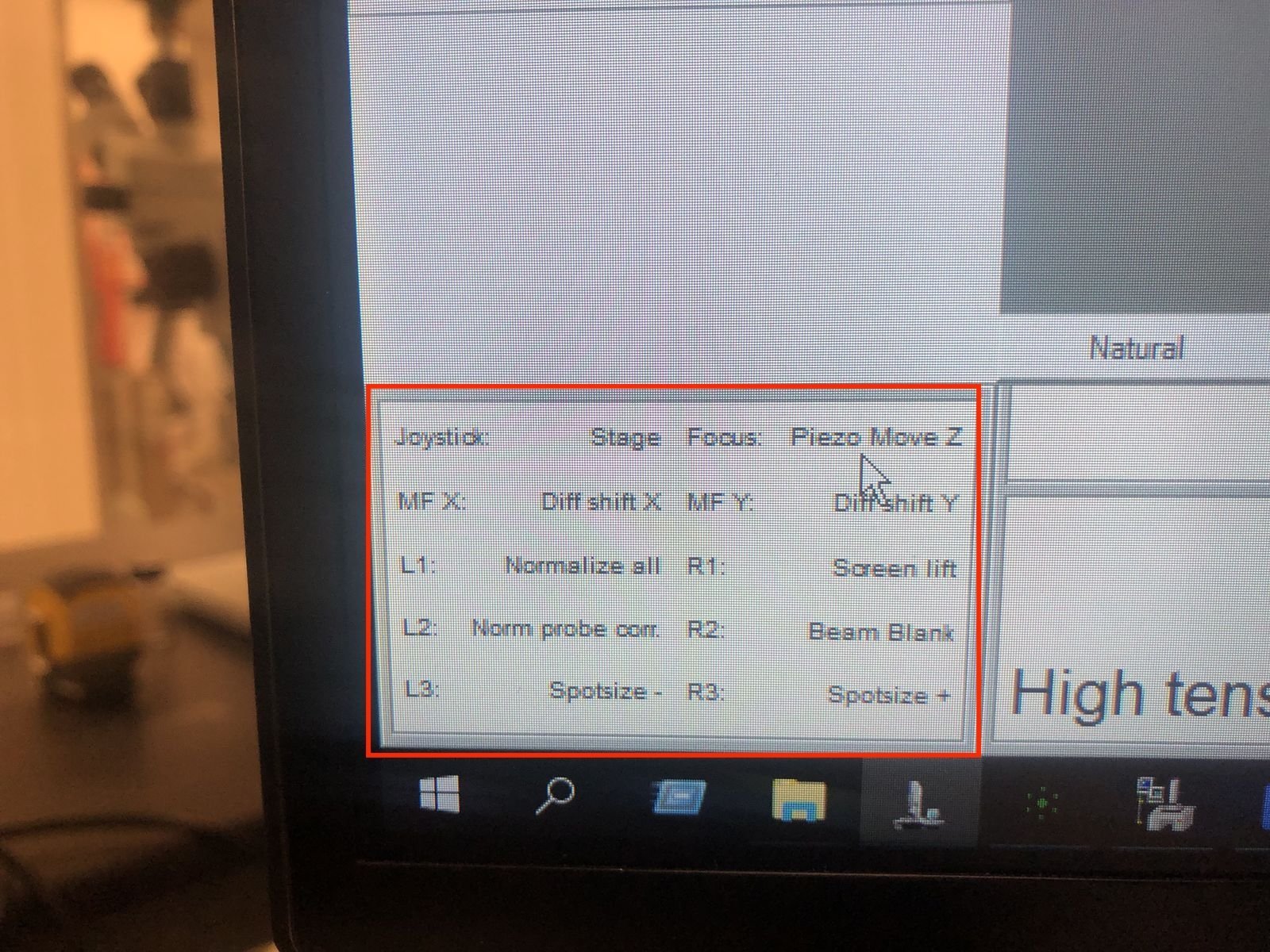
Hand panel R1, R2, R3 values:
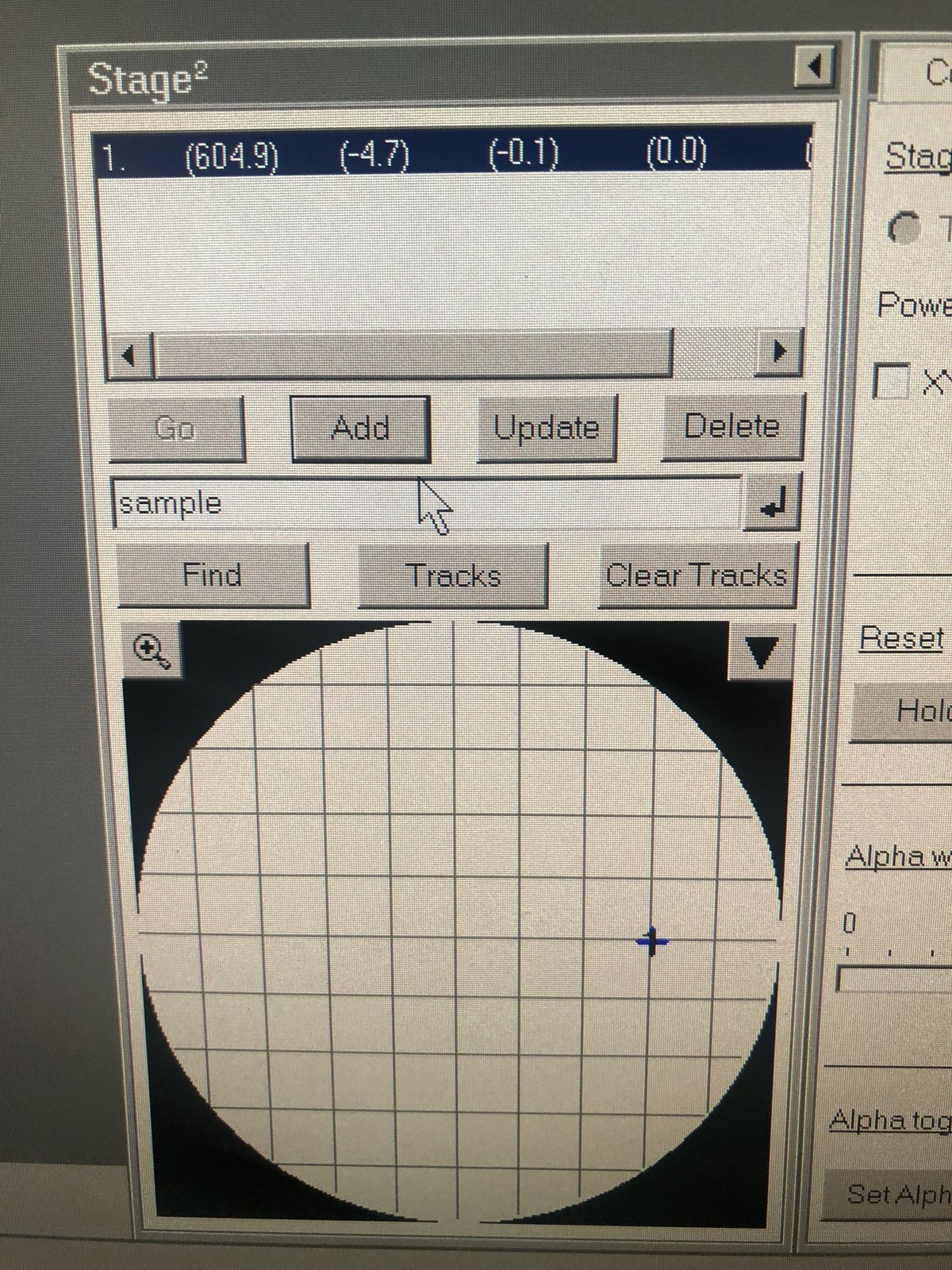
Stage position and coordinates:
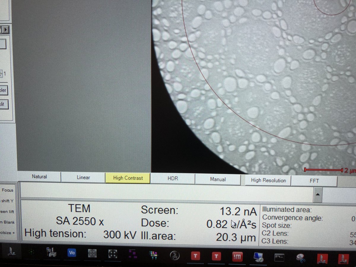
Dose rate and TEM mode display:
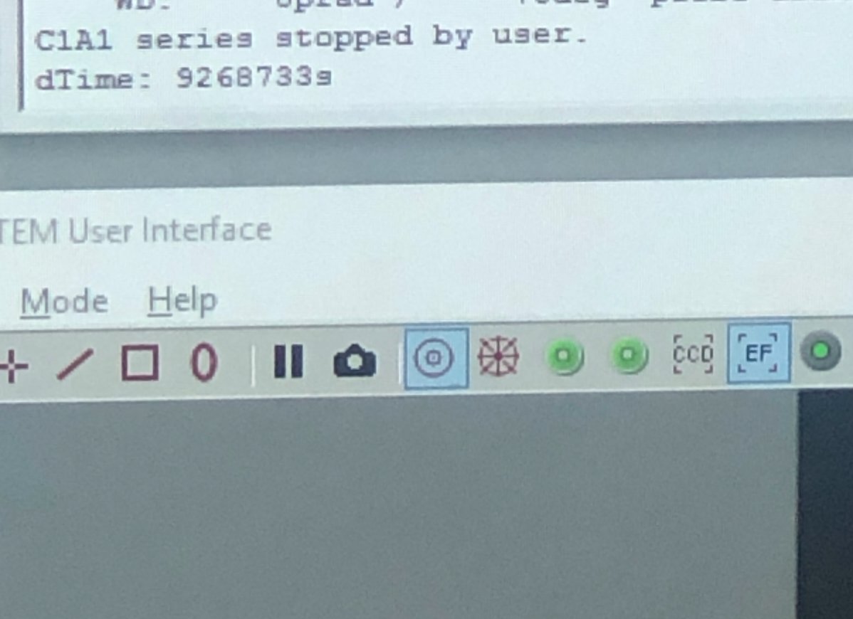
HAADF detector on TEMUI:
Samples with holes:
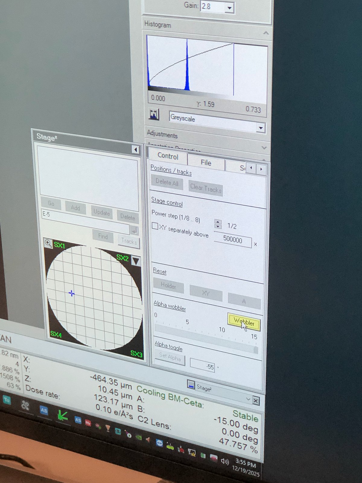
Wobbler to check eucentric height:
At eucentric height, tilting the holder should induce minimal shift.
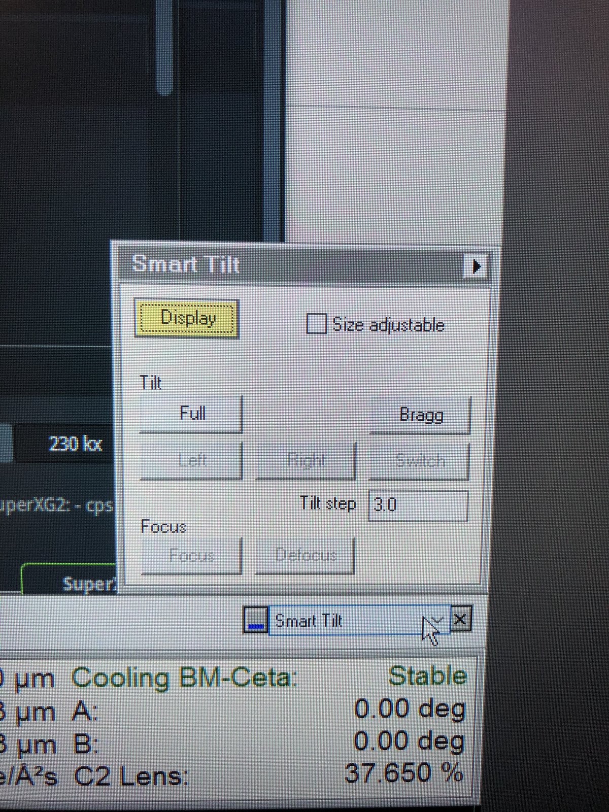
Smart tilt:
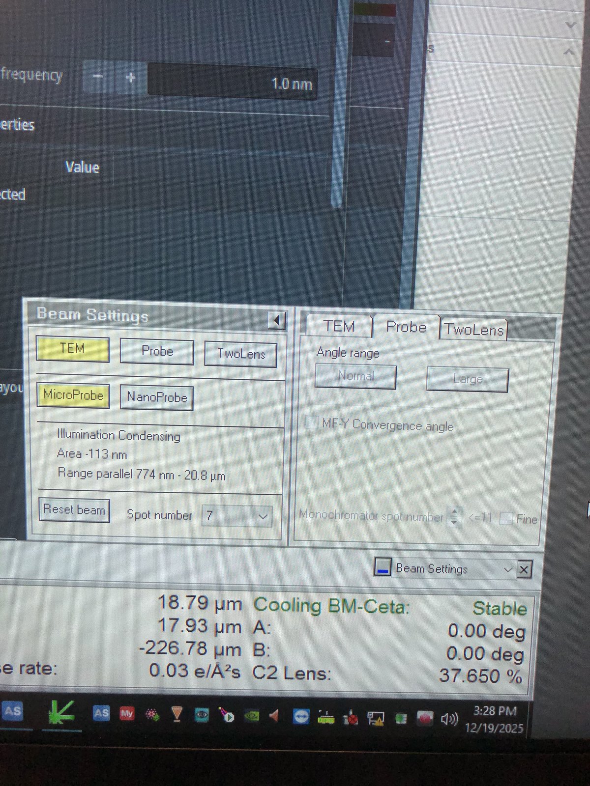
Beam setting in Quick tab:
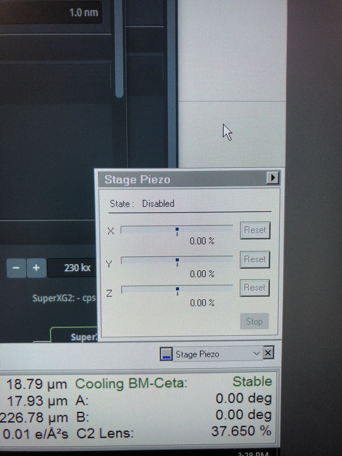
Stage piezo in Quick tab:
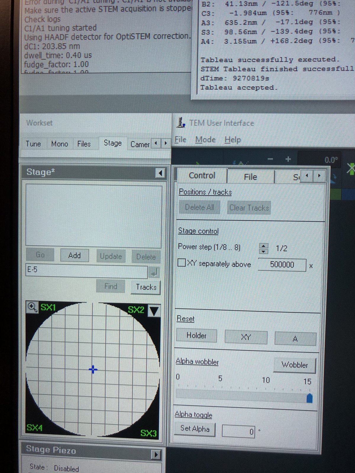
Stage tab:
Troubleshooting
Common problems encountered during TEM sessions.
| Problem | Cause | Solution |
|---|---|---|
| Beam is not round after C2 alignment | Condenser astigmatism | Go to Stigmator, then Condenser, adjust mulXY knobs |
| Beam shifts when changing magnification | Beam Shift not set | Use Direct Alignment, then Beam Shift to store center position |
| Image drifts when tilting | Eucentric height not set | Re-do eucentric height (1.3) |
| C1A1 shows orange for C1 | Focus too far from target | Manually adjust Z-axis during iteration |
| Tableau values outside specification | Higher-order aberrations uncorrected | Run additional Tableau iterations, reduce Auto correct to 75% |
| Gray image in Velox during C1A1 | Intensity too low for corrector | Adjust intensity knob to 800-900 counts during iteration |
| No beam visible after opening column valves | Beam is blanked or screen not inserted | Check beam blank status, verify screen position |
FAQ
Convergence angle: In TEMUI, go to Beam Setting, then Probe, and use the mulXY knobs to adjust.
Tableau and C1A1: Tableau measures aberrations visually across multiple tilt angles. C1A1 corrects first-order aberrations (defocus and astigmatism). Run C1A1 first, then Tableau for higher-order corrections.
Underfocus direction: Counterclockwise on hand panel, Z-axis down.
Eucentric height: The z-position where tilting does not shift the sample. At eucentric height, defocus = 0 and probe size is smallest relative to the sample.
Beam Shift vs hand panel ball: Beam Shift stores the center position internally, so the beam stays centered when changing magnification. The hand panel ball moves the beam but does not save the position.
Underfocus vs overfocus: Underfocus produces bright white Fresnel fringes at edges. Overfocus inverts the contrast with dark fringes.
Monochromator: Filters the electron beam to select a narrow energy range, improving energy resolution for EELS and reducing chromatic aberration.
Two-lens vs three-lens mode: Two-lens mode (C1+C2) turns off C3, providing a simpler beam path for C2 aperture alignment. Three-lens mode (C1+C2+C3) is the standard operating mode for TEM imaging.
Objective lens in TEM: In TEM, the objective lens sits below the sample and forms the first magnified image. In STEM, it sits above the sample and focuses the probe.
C2 aperture purpose: The C2 aperture blocks off-axis electrons, controlling the convergence angle and beam current. It must be centered on the optical axis for symmetric beam expansion.
References
Changelog
- Mar 1, 2026 - Restructure to match STEM guide format with subsections, checklists, and troubleshooting table
- Dec 15, 2025 - Add pre-probe corrector with STEM Direct Alignment steps by @bobleesj
- Dec 12, 2025 - Add STEM training images by Guoliang Hu
- Dec 8, 2025 - First draft of Spectra training by @bobleesj